
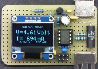
OLED USB Voltage and Current Meter - UPDATED!
These devices can be bought for a few Euros, but I'm a DIYer and wanted to try to make it work with a small OLED display, an ATtiny85 microcontroller and a few passive components.
These devices can be bought for a few Euros, but I'm a DIYer and wanted to try to make it work with a small OLED display, an ATtiny85 microcontroller and a few passive components.
Thanks to these libraries ,TinySSD1306 and TinyWireM, to manage the display functions through the I2C interface and effective smoothing routine, all found on the net, I didn’t get a precision instrument but a result I find interesting.
The basic idea is to read the voltage drop across a low value resistor in series with the load on the ground side, due to the Attiny85 ADC, set as Unipolar Differential Conversion mode, 20x gain, Vref 1.1V internal, to calculate the current through the load.
With a 0.1 Ohm Rsense you can read a maximum current of about 500 mA with a resolution of 10 mA before saturating the ADC input. For higher currents the ADC is set for a unitary gain, a kind of autorange.
The maximum reading can be 10 A but the Rsense dissipation and the USB connectors current capacity are to be considered, so I think that 1 A is quiet enough.
To read the voltage the ADC is set as Single Ended Conversion mode and the input voltage divider is set at Vcc level from vccOut pin, which remains grounded during the current measurement.
The current and voltage’s reading occurs sequentially within the Loop with a delay, determining the number of readings, which basically depends on the display routine. The smoothing function helps to have a more stable data visualization. Accuracy also depends on the actual Vref and voltage divider values, which can be experimentally varied to improve.
UPDATE 13-02-2016
- Added a 3.3 Volt voltage regulator to isolate the microcontroller power supply from the usb Vcc bus, improving the internal reference voltage stability and thus the precision of the measurement.
- Added a mosfet to drive the voltage divider and calculated it again to obtain a useful measurement range from 4.00 to 6.00 Volt (a screenshot is attached to better explain the operation).
- Added the measurement of instantaneous power (Watt) and total electric charge (mAh).
- Some minor code fixes.
More details in the code comments and in the Attiny85 datasheet.
The code has been written using Arduino IDE 1.6.6 plus ATtiny Boards Manager and loaded via USBasp.
I'll attach some pictures, schematics, libraries, the sketch and the firmware of the project.
Best regards, Anto
Discussie (3 opmerking(en))