
Artikel
Lead-acid battery activator 0-30V
Also shows the battery quality
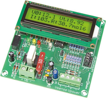
A well-known electronics store has been selling a very simple lead-acid battery activator for many years. Although I can't prove it, my lead-acid batteries do seem to last longer since I started using the activator. The principle behind this circuit is very simple. The battery is loaded with a current of about 100 A for a period of 100 µs, which is repeated every 30 seconds. But this circuit is capable of more, which we'll show you in this article.
Gerber bestand
De PCB bij dit artikel is als Gerber file beschikbaar gesteld. Elektor Members kunnen exclusief deze files gratis downloaden en gebruiken om de PCB zelf af te drukken met geschikte apparatuur óf de Gerber te laten drukken via een dienstverlener.
Elektor kan u bijvoorbeeld de PCB Service van onze partner Eurocircuits van harte aanbevelen of AISLER.
TIP: Uw eerste PCB tot € 30 is gratis bij AISLER indien u bij het afrekenen gebruik maakt van coupon code ELCCBB.
Het gebruik van onze Gerber files is vrijgegeven onder een Creative Commons- licentie. Creative Commons biedt auteurs, wetenschappers en andere creatieve makers de vrijheid om op een flexibele manier met hun auteursrechten om te gaan.
PCB
Extra info / Update
Tags
Hobby & modeling
Batteries, test & measurement
Level
Advanced
Time taken
About 3 hours
Required tools
No special tools are required
Cost
About € 60
Hobby & modeling
Batteries, test & measurement
Level
Advanced
Time taken
About 3 hours
Required tools
No special tools are required
Cost
About € 60
Onderdelenlijst
In the Store
160064-1 PCB
160064-41 Programmed controller
160064-71 Kit of parts
120061-74 2x16 character LCD
Parts List
Resistors:
(0.25W, 250 V, unless otherwise stated)
R1,R25 = 10 k
R2...R19 = 22 k, 1%, 0,6 W, 350 V
R20...R22 = 1 k
R23,R24 = 560 Ohm
R27 = 50 mOhm, 1 W, MPC75
R26 = 390 Ohm
P1 = 10 k, preset
Capacitors:
C1 = 2.2 µ, 50 V, 2 mm pitch, 5x11 mm
C2,C8 = 10 µ, 50 V, 2 mm pitch, 5x11 mm
C3...C6 = 100 n, 50 V, X7R, 5.08 mm pitch
Semiconductors:
D1,D2,D7,D8 = BAT85
D3...D6 = BZX79-C2V4
D9 = SR1204
D10 = BZX55C15V
LED1 = led, blue, 3 mm
LED2 = led, red, 3 mm
LED3 = led, yellow, 3 mm
LED4 = led, green, 3 mm
T1 = IRLB8721PBF
IC1 = LP2950ACZ-5.0
IC2 = PIC16F1847-I/P, programmed (EPS 160064-41)
IC3 = RO-0515S/P
IC4 = VO615A
Miscellaneous:
F1 = PCB-mount fuse holder + fuse (see text)
LCD1 = LCD, 2x16 characters, EPS 120061-74
LCD1 = 16-pin header, vertical, 0.1” pitch
LCD1 = 16-pin header bus, vertical
K1,K2 = 2-way PCB screw terminal, 0.2” pitch
K3 = 2-way PCB screw terminal, 0.3” pitch
JP1...JP4 = 3-way header, vertical, 0.1” pitch
JP5 = 2-way header, vertical, 0.1” pitch
Jumper for JP5
2x5 header bus, vertical for JP1...JP5
IC socket, DIP-18, for IC2
PCB 160064-1 v2.1
Discussie (0 opmerking(en))