

Due to their inherent versatility and wideband frequency response, spiral slot antennas have a variety of applications for different microwave frequency bands. For example, these antennas are used for wireless communication, sensing, positioning, and tracking. To optimize the design of spiral slot antennas, engineers can use electromagnetics analysis to accurately calculate characteristics such as S-parameters and far-field patterns.
The Benefits of Spiral Slot Antennas
Spiral slot antennas have several advantages, including:
- Nearly perfect circularly polarized radiation
- A wideband frequency response
- The ability to maintain a consistent radiation pattern and impedance over a large bandwidth
In addition, the design of spiral slot antennas allows them to be conformally mounted on a variety of objects. This is useful in, for example, the defense industry, where spiral slot antennas can be mounted on military automobiles and aircraft and used for communication and surveillance purposes.
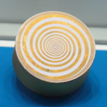
Example of a spiral antenna. Image by Bin im Garten — Own work. Licensed under CC BY-SA 3.0, via Wikimedia Commons.
While there are multiple types of spiral antennas, one of the most common is the Archimedean spiral antenna. Here, we discuss modeling this antenna with the COMSOL Multiphysics® software and add-on RF Module.
Evaluating the Design of a Spiral Slot Antenna with COMSOL Multiphysics®
Let’s start by examining the geometry of the spiral slot antenna, which consists of a two-arm Archimedean spiral slot. We use parametric curves to create the spiral pattern on a single-sided metal substrate. The parametric curves provide the freedom to draw an arbitrary line shape by using a mathematical formulation. The substrate is a perfect electric conductor (PEC) with a very high conductivity and negligible losses on the surface. At the center of the spiral slot is a lumped port, which is used to excite the antenna.


Spiral slot antenna geometry (left) and mesh (right).
The antenna and substrate are surrounded by an air region and perfectly matched layer (PML), the latter of which is depicted in gray in the left image above. The physics-controlled mesh, which is shown in the right image above, is generated by default. Here, the maximum mesh size is set to 0.2 wavelengths, which is based on the maximum frequency defined in a Frequency Domain study step. The mesh is also automatically scaled by material properties such as the permittivity and permeability inside the dielectric substrate. The PML is swept with five elements along the radial direction.
Examining the Results of the Electromagnetics Simulation
The first plot looks at the electric field norm at the antenna’s top surface. This plot shows more intense electric fields along the slot than over the rest of the antenna surface, confirming that the fields are well confined to the slotted substrate.
Next, we examine a plot of the calculated S-parameters. From the results, we determine that over the studied frequency range, S11 is around -10 dB.


The log-scaled electric field norm on the xy-plane (left) and an S-parameter plot (right).
To perform a far-field analysis, we first create a 2D polar plot. This plot enables us to visualize the bidirectional radiation patterns of the antenna at different frequencies. We see that the shape of the radiation pattern remains similar for different frequencies.
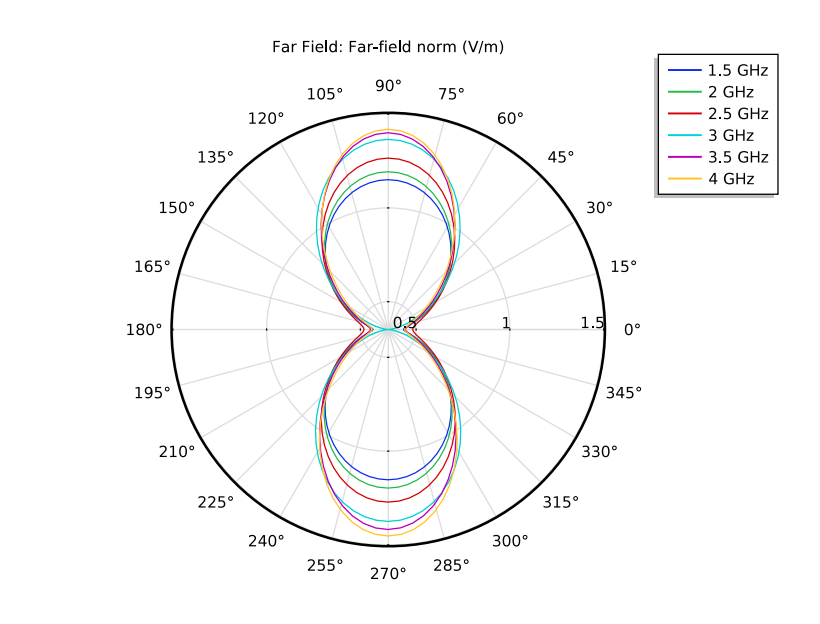
Polar plot on the yz-plane.
Finally, we examine the bidirectional far-field radiation pattern in 3D at a frequency of interest (3 GHz in this case). The results suggest that the direction of maximum radiation is along the z-axis. In addition, we see a symmetric pattern in the far field.


The 3D far-field radiation pattern of the antenna at 3 GHz (left) along with the antenna (right).
Next Steps
To get started with modeling spiral slot antennas, click the button below. Doing so will take you to the Application Gallery, where you can log into your COMSOL Access account and download the MPH file and step-by-step instructions for the example.


Comments (0)