PC USB Logic Analyzers with Arduino, Raspberry Pi, and Co.
Step-by-step instructions guide you through the analysis of modern protocols such as I²C, SPI, UART, RS-232, NeoPixel, WS28xx, HD44780 and 1-Wire protocols. With the help of numerous experimental circuits based on the Raspberry Pi Pico, Arduino Uno and the Bus Pirate, you will learn the practical application of popular USB logic analyzers.
All the experimental circuits presented in this book have been fully tested and are fully functional. The necessary program listings are included – no special programming or electronics knowledge is required for these circuits. The programming languages used are MicroPython and C along with the development environments Thonny and Arduino IDE.
This book uses several models of flexible and widely available USB logic analyzers and shows the strengths and weaknesses of each price range.
You will learn about the criteria that matter for your work and be able to find the right device for you.
Whether Arduino, Raspberry Pi or Raspberry Pi Pico, the example circuits shown allow you to get started quickly with protocol analysis and can also serve as a basis for your own experiments.
After reading this book, you will be familiar with all the important terms and contexts, conduct your own experiments, analyze protocols independently, culminating in a comprehensive knowledge set of digital signals and protocols.
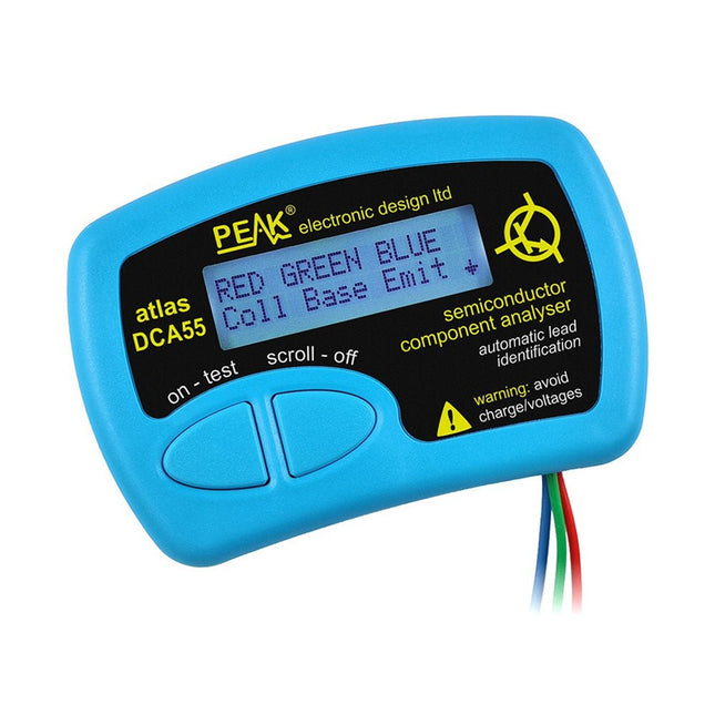
The Peak Atlas DCA55 is great for automatically identifying the type of semiconductor on the test leads as well as the pinout and many other parameters.
Supports transistors MOSFETs, JFETs (gate pin only can be identified), diodes, LEDs and lots more. Automatically identifies type of component, pinout and other important parameters. Now features transistor leakage measurement and Germanium/Silicon identification.
Component Support
Bipolar transistors (NPN/PNP inc Silicon/Germanium)
Darlington transistors (NPN/PNP)
Enhancement mode MOSFETs (N-Ch and P-Ch)
Depletion mode MOSFETs (N-Ch and P-Ch)
Junction FETs (N-Ch and P-Ch). Only gate lead identified.
Diodes and diode networks (2 and 3 lead types).
LEDs and bi-colour LEDs (2 lead and 3 lead types).
Low power sensitive Triacs and Thyristors (<5 mA trigger and hold)
Measurements
Part type identification
Pinout identification
BJT current gain (hFE)
BJT base emitter voltage (Vbe)
BJT collector leakage current
MOSFET gate threshold voltage
Diode forward voltage drop (Vf)
Specificaties
Analyzer type
Transistors, Diodes, LEDs, MOSFETs, JFETs
Pinout detection
Full pinout (only Gate on JFETs)
Pinout configuration
Connect any way round
Transistor measurements
Vbe, hFE, Iceo
MOSFET measurements
Vgs(on)
Diode measurements
Vf
Probe type
Universal grabber type
Battery
Single AAA cell (supplied). Life typically 1300 ops
Test conditions
Typically 5 mA, 5 V peak
Display type
Alphanumeric LCD (with backlight)
Inbegrepen
DCA55 Semiconductor Component Analyser instrument
Comprehensive illustrated user guide
Fitted universal hook probes
AAA Alkaline battery
Downloads
Datasheet (EN)
User Guide (EN)
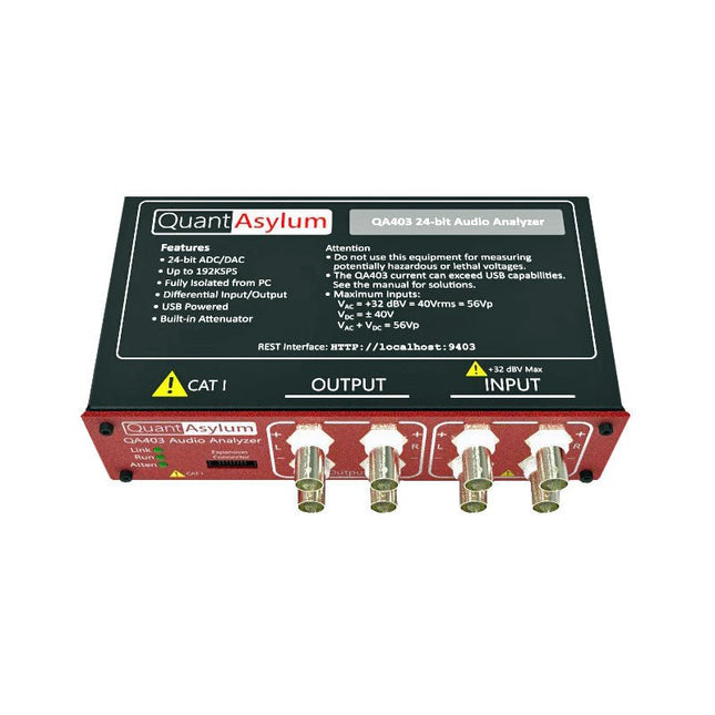
De QA403 is de vierde generatie audio analyzer van QuantAsylum. Deze QA403 verhoogt de functionaliteit van de QA402 met verbeterde ruis- en vervormingsprestaties, en ook een vlakkere respons aan de randen van de band. Het compacte formaat van de QA403 zorgt ervoor dat u hem vrijwel overal mee naartoe kunt nemen.
Kenmerken
24-bits ADC/DAC
Tot 192 kSPS
Volledig geïsoleerd van de PC
Differentiële input/output
USB gevoed
Ingebouwde demping
Snel opstarten en geen stuurprogramma
De QA403 is een USB-apparaat zonder stuurprogramma's, wat betekent dat hij meteen operationeel is zodra u hem aansluit. De software is gratis, en u kunt snel en gemakkelijk de hardware van de ene machine naar de andere verplaatsen. Dus als u naar een vestiging moet om een probleem op te lossen, of de QA403 mee naar huis dient te nemen op een thuiswerkdag, dan kunt u dit zonder veel gedoe doen.
No-Cal ontwerp
De QA403 wordt geleverd met een fabriekskalibratie in het flashgeheugen, waardoor consistente prestaties bij gebruik van meerdere analyzers kan worden gegarandeerd. Op uw productielijn kunt u een andere QA403 installeren en erop vertrouwen dat wat u op de ene analyzer leest overeenkomt met de andere. Er hoeft dus niet geregeld herkalibratie plaats te vinden.
Metingen
Het uitvoeren van basismetingen kan snel en eenvoudig. In een paar klikken krijgt u inzicht in de frequentierespons, de THD (+ N), de versterking, de SNR, en andere gegevens van uw geteste apparaat.
Dynamisch bereik
De QA403 biedt 8 gradaties aan versterking op de ingang (0 tot +42 dBV in 6 stappen) en 4 stappen versterking op de uitgang (-12 tot +18 dBV in stappen van 10 dB). Dit zorgt voor consistente prestaties over zeer brede in- en uitgangsniveaus. De maximale AC ingangsspanning op de QA403 is +32 dBV = 40 Vrms. De maximale DC is ±40 V en de maximale ACPEAK + DC = ±56 V.
Eenvoudig te programmeren
De QA403 ondersteunt een REST-interface, waardoor het eenvoudig is om metingen te automatiseren in vrijwel elke taal. Van Python tot C++ tot Visual Basic: als u weet hoe u een webpagina in uw favoriete taal moet laden dan kunt u al de QA403 op afstand bedienen. Metingen zijn snel en responsief, doorgaans met het verwerken van tientallen opdrachten per seconde.
Geïsoleerd, en gevoed via USB
De QA403 werkt geïsoleerd van de pc, wat betekent dat u echt uw te testen apparaat meet, en niet met een fantoom aardlus te doen heeft. De QA403 wordt gevoed via USB, zoals bijna alle QuantAsylum instrumenten. Indien u op afstand moet configureren, neem dan een hub met voeding mee in uw tas en uw hele testopstelling kan dan functioneren met een minimum aan kabels.
Vaarwel geluidskaart, hallo QA403
Moe van het proberen om een geluidskaart aan de praat te krijgen? Nachtmerries van het kalibreren? Gemis van de juiste versterking? Of te weinig aansturing? Bent u het zat om met vaste ingangsranges om te gaan? Of bang dat u zaken kapot maakt met te veel DC of AC? Moe van de aardlussen? Dáarom heeft QuantAsylum de QA403 ontworpen.
Specificaties
Afmetingen
177 x 44 x 97 mm (B x H x D)
Gewicht
435 g
Case Materiaal
Aluminium met poedercoating (2 mm dik voorpaneel, 1.6 mm dikke boven/onderkant)
Downloads
Datasheet
Gebruikershandleiding
GitHub
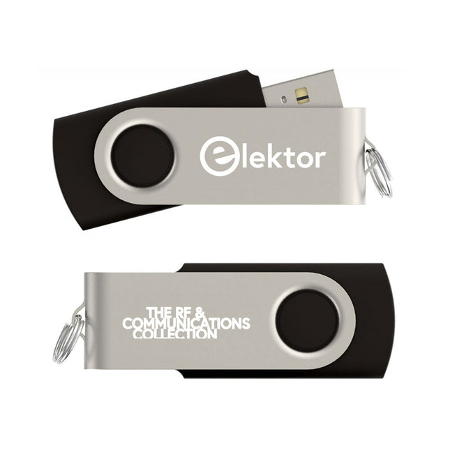
Op deze USB-stick vindt u een selectie van meer dan 350 artikelen over RF, radio en communicatie, gepubliceerd in Elektor Magazine. De inhoud bestaat uit zowel achtergrondartikelen als projecten met de volgende onderwerpen:
Basisradiogerelateerde circuits, maar ook complexere circuits zoals filters, oscillatoren en versterkers.
Ontwerp, constructie en theorie van antennes voor het efficiënt verzenden en ontvangen van radiosignalen.
Ontwerp en analyse van RF-circuits, waaronder filters, mixers, PLL's en frequentiesynthesizers. Hulpmiddelen en technieken voor het voorspellen van de voortplantingspaden van radiogolven en het meten van de RF-signaalsterkte.
Technieken voor het verwerken van digitale signalen in RF-systemen, inclusief modulatie- en demodulatiemethoden.
Projecten op radio-ontvangers, AM, FM, SSB, CW, DRM, DAB, DAB+, Software Defined Radio en meer.
Projecten over Wi-Fi, Bluetooth, LoRaWAN en meer.
U kunt de artikelzoekfunctie gebruiken om specifieke inhoud in de volledige tekst te vinden. De resultaten worden altijd weergegeven als vooraf opgemaakte PDF-documenten. U kunt Adobe Reader gebruiken om door artikelen te bladeren, en u kunt de geïntegreerde zoekfuncties van Adobe Reader gebruiken om exemplaren van afzonderlijke woorden en uitdrukkingen te vinden.
PC USB Logic Analyzers with Arduino, Raspberry Pi, and Co.
Step-by-step instructions guide you through the analysis of modern protocols such as I²C, SPI, UART, RS-232, NeoPixel, WS28xx, HD44780 and 1-Wire protocols. With the help of numerous experimental circuits based on the Raspberry Pi Pico, Arduino Uno and the Bus Pirate, you will learn the practical application of popular USB logic analyzers.
All the experimental circuits presented in this book have been fully tested and are fully functional. The necessary program listings are included – no special programming or electronics knowledge is required for these circuits. The programming languages used are MicroPython and C along with the development environments Thonny and Arduino IDE.
This book uses several models of flexible and widely available USB logic analyzers and shows the strengths and weaknesses of each price range.
You will learn about the criteria that matter for your work and be able to find the right device for you.
Whether Arduino, Raspberry Pi or Raspberry Pi Pico, the example circuits shown allow you to get started quickly with protocol analysis and can also serve as a basis for your own experiments.
After reading this book, you will be familiar with all the important terms and contexts, conduct your own experiments, analyze protocols independently, culminating in a comprehensive knowledge set of digital signals and protocols.
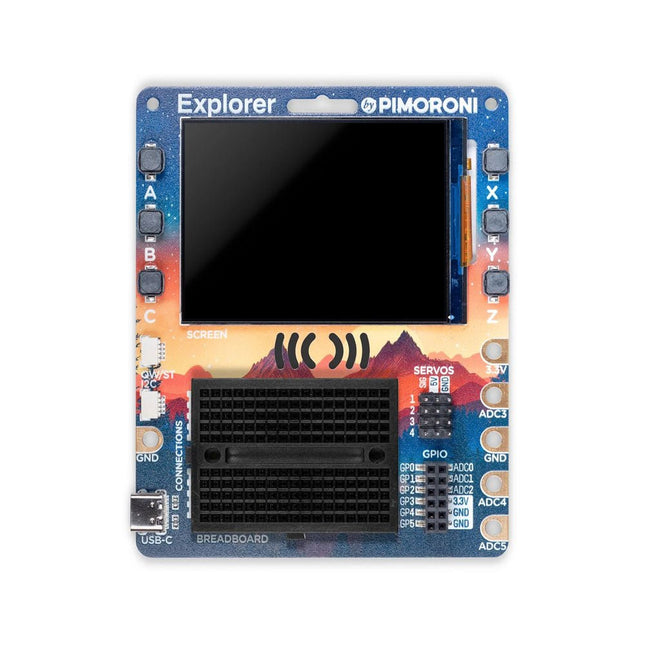
De Pimoroni Explorer Starter Kit is een elektronische avonturenspeeltuin voor fysiek computergebruik, gebaseerd op de RP2350-chip. Het bevat een 2,8-inch LCD-scherm, een luidspreker, een mini-breadboard en nog veel meer. Het is ideaal voor knutselen, experimenteren en het bouwen van kleine prototypes.
Kenmerken
Mini-breadboard voor het aansluiten van componenten
Servoheaders
Analoge ingangen
Ingebouwde luidspreker
Veel algemene invoer/uitvoer
Connectoren voor het bevestigen van krokodillensnoeren
Qw/ST-connectoren voor het bevestigen van I²C-breakouts
Specificaties
Aangedreven door RP2350B (Dual Arm Cortex-M33 met een snelheid tot 150 MHz met 520 KB SRAM)
16 MB QSPI-flash met ondersteuning voor XiP
2,8" IPS LCD-scherm (320 x 240 pixels)
Stuurprogramma-IC: ST7789V
Helderheid: 250 cd/m²
Actief gebied: 43,2 x 57,5 mm
USB-C-connector voor programmeren en voeding
Mini-broodplank
Piezo-luidspreker
6x door de gebruiker bestuurbare schakelaars
Reset- en opstartknoppen
Gemakkelijke toegang tot GPIO-headers (6x GPIO's en 3x ADC's, plus 3,3 V voeding en aarde)
6x krokodillenklemterminals (3x ADC's, plus 3,3 V stroom en aarding)
4x 3-pins servo-uitgangen
2x Qw/ST (Qwiic/STEMMA QT)-connector
2-pins JST-PH-connector voor het toevoegen van een batterij
Gleuf voor sleutelkoord!
Inclusief 2x bureaustandaardvoeten
Volledig gemonteerd (solderen niet nodig)
Programmeerbaar met C/C++ of MicroPython
Inbegrepen
1x Pimoroni Explorer
1x Multi-Sensor Stick – een fraaie nieuwe alles-in-één supersensorsuite voor omgevings-, licht- en bewegingsdetectie
Selectie van verschillende gekleurde LED's om mee te knipperen (inclusief rood, geel, groen, blauw, wit en RGB)
1x Potentiometer (voor analoog amusement)
3x 12 mm schakelaars met verschillende gekleurde kapjes
2x Servo's met continue rotatie
2x 60 mm wielen voor bevestiging aan uw servo's
1x AAA-batterijhouder (batterijen niet inbegrepen)
1x klittenband om de batterijhouder aan de achterkant van de Explorer te bevestigen
20x pin-naar-pin- en 20x pin-naar-socket-jumperdraden voor het maken van verbindingen op uw breadboard
1x Qw/ST-kabel om de Multi-Sensor Stick aan te sluiten
1x Siliconen USB-C kabel
Downloads
GitHub
Schematic
De USB-CAN-FD is een hoogwaardige industriële USB-naar-CAN-FD-adapter, CAN/CAN-FD bus communicatie-interfacekaart en CAN/CAN-FD protocoldata analysator. Aan boord dubbele onafhankelijke CAN-FD interfaces met elektrische isolatie en meerdere beveiligingscircuits. Ondersteunt Windows, wordt geleverd met stuurprogramma's, CAN-FD Tools gerelateerde software, secundaire ontwikkelingsvoorbeelden en tutorials.Het kan via een USB-poort worden aangesloten op een pc of industriële besturingshost om transceiverbesturing, gegevensanalyse, verzameling en bewaking van CAN/CAN-FD-busnetwerk te realiseren. Het apparaat is compact en gebruiksvriendelijk en kan worden gebruikt voor het leren en debuggen van de CAN/CAN-FD-bus en voor secundaire ontwikkeling en integratie in diverse industriële, energiecommunicatie- en intelligente besturingstoepassingen die CAN/CAN-FD-bus communicatie vereisen.Specificaties
Soort product
Industriële kwaliteit: USB naar CAN-FD interfaceconverter, CAN/CAN-FD bus communicatie-interfacekaart, CAN/CAN-FD protocoldata analysator
USB
Bedrijfsspanning
5 V (rechtstreeks van de USB-poort zonder externe voeding)
Aansluiting
USB-B
CAN/CAN FD-interface
CAN/CAN FD-kanaal
Tweekanaals: CAN1 en CAN2 (onafhankelijk en volledig geïsoleerd, isolatie spanning: 3000 V DC)
Aansluiting
CAN-bus schroefklem (OPEN6 5,08 mm steek)
Afsluitweerstand
Elk CAN/CAN-FD-kanaal heeft twee ingebouwde 120? afsluitweerstanden, die kunnen worden ingeschakeld met een schakelaar
Baudrate
100Kbps~5Mbps (configureerbaar via software)
Protocol ondersteuning
CAN2.0A, CAN2.0B en ISO 11898-1 CAN-FD protocol V.1.0
Overdrachtssnelheid
De ontvangst- en verzendsnelheid van elk CAN/CAN-FD-kanaal kan 20000 frames/s en 5000 frames/s bereiken.
Buffer voor verzenden
1500 frames ontvangstbuffer en 64 frames zendbuffer per kanaal (automatisch opnieuw zenden als de verzending mislukt)
Indicatoren
PWR
Voedingsspanning
SYS
Systeemstatus, normaal uit; blijft aan als er een bus fout is
CAN1
CAN1-kanaalindicator (knippert bij verzenden en ontvangen van data)
CAN2
CAN2-kanaalindicator (knippert bij verzenden en ontvangen van data)
Systeemondersteuning
Windows
Windows XP/7/8/10/11 (32/64 bits); biedt nog geen ondersteuning voor Linux; de bijbehorende stuurprogramma's zijn in ontwikkeling.
Bedrijfstemperatuur
?40 tot +85°C
Materiaal behuizing
Aluminium behuizing + 3D vlamwerende isolatieplaten aan beide zijden (Dit ontwerp kan een betere bescherming bieden tegen elektrische ontladingen, verbetert de veiligheid van het product en verlengt de levensduur)
Afmetingen
104 x 70 x 25 mm
Inbegrepen
Waveshare USB-CAN-FD
USB-A naar USB-B kabel
4-pins kabel
Schroevendraaier
DownloadsWiki
RF circuit design is now more important than ever as we find ourselves in an increasingly wireless world. Radio is the backbone of today’s wireless industry with protocols such as Bluetooth, Wi-Fi, WiMax, and ZigBee. Most, if not all, mobile devices have an RF component and this book tells the reader how to design and integrate that component in a very practical fashion. This book has been updated to include today's integrated circuit (IC) and system-level design issues as well as keeping its classic ‘wire lead’ material.
Design Concepts and Tools Include
The Basics: Wires, Resistors, Capacitors, Inductors
Resonant Circuits: Resonance, Insertion Loss
Filter Design: High-pass, Bandpass, Band-rejection
Impedance Matching: The L Network, Smith Charts, Software Design Tools
Transistors: Materials, Y Parameters, S Parameters
Small Signal RF Amplifier: Transistor Biasing, Y Parameters, S Parameters
RF Power Amplifiers: Automatic Shutdown Circuitry, Broadband Transformers, Practical Winding Hints
RF Front-End: Architectures, Software-Defined Radios, ADC’s Effects
RF Design Tools: Languages, Flow, Modeling
We've incorporated tinkering essentials like a mini breadboard, motor drivers, ADC inputs, a built in speaker, general purpose inputs/outputs, switches, and two Breakout Garden slots so you can add on a couple of breakouts.We've also managed to fit in a vibrant 240x240 IPS LCD screen with four tactile buttons so you can easily monitor and control what your project is doing. It's all wrapped up in a nice, sturdy baseboard with a pleasingly compact footprint which won't involve nearly as many trailing wires as if you were experimenting with a traditional breadboard setup.Our comprehensive MicroPython and C++ libraries will let you control every aspect of the board like a digital maestro. It's great for beginners and advanced users.Features
Pico Explorer Base
Piezo speaker
1.54' IPS LCD screen (240x240)
Four user-controllable switches
Two Half-Bridge motor drivers (with over current indicator LED)
Easy access GPIO and ADC pin Headers
Two Breakout Garden I²C sockets
Mini breadboard
Rubber feet
Compatible with Raspberry Pi Pico
No soldering required (as long as your Pico has header pins attached).
Dimensions: approx 117 x 63 x 20 mm (L x W x H, assembled)
C/C++ and MicroPython libraries
Schematic