DIY Christmas Fireplace: A 3D Puzzle with PCBs, LEDs, and Raspberry Pi Pico
Want a fun Christmas project? Elektor has you covered. This DIY Christmas fireplace comprises PCBs, an LED matrix, and a Raspberry Pi Pico.
One of the joys of this cold and frosty time of year is warming your toes and enjoying a glass of mulled wine next to a blazing log fire. But not everyone has a fireplace at home or wants to add to environmental pollution. The holiday project this year is to build a miniaturized DIY Christmas fireplace that sits on your desk, using an LED matrix to produce the flickering flame effect with a Raspberry Pi Pico in control.
An Electronic Solution?
Every year, when we first hear the notes of “Fairytale of New York,” we know Christmas can’t be far off, even though this year the traditional festive get-together will be moderated by the need to reduce the spread of COVID-19. Anyone thinking of holiday-related electronics projects will certainly recall one or two flashing Christmas tree designs that Elektor has featured in the past. Last year, my colleague Luc Lemmens presented an Electronic Candle that could be "lit" and blown out.
With many people still working from home, our plan is to conjure up feelings of "hygge" at your desk by simulating the flickering flames of an open fire using an LED matrix and a Raspberry Pi Pico. You will not be able to roast any chestnuts using this design (unless something goes seriously wrong with your circuit), but you can enjoy the relaxing effect we achieved.
But how do we go about designing and building a DIY Christmas fireplace? Keep reading to find out how I got on and what didn’t quite go quiet according to plan during the build.
3D Modeling Using FreeCAD
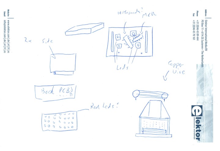
The deadline for the Christmas project always comes as a bit of a surprise — to me, at least. Who would have guessed, at the start of the year, that Christmas day would fall on December 25? Anyway, enough excuses. Some parts of this project are not yet completely finished. Just like my annual last-minute dash to buy all the presents in time, there are one or two unfinished aspects of this design, so it does not qualify as a complete Elektor Project. With that in mind, I hope you enjoy reading about the project, including the things that did not go according to plan (just like every Christmas). Refer to Figure 1 for a rough sketch of the DIY Christmas fireplace.
Figure 1: Sketch of the initial idea.
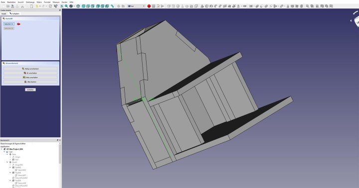
You can get an idea of the proportions and the final design, with side walls, a mantelpiece and a chimney breast. This concept is now converted into a 3D model with dimensions that can be updated as required. In addition to commercial CAD tools such as Inventor, SolidWorks or Fusion 365 or OpenSCAD, there is also FreeCAD. Even though the version number at 0.19 is nowhere near 1.0, you shouldn't be fooled: the current version of FreeCAD is a solid build. If you want to start using FreeCAD, we recommend the tutorials, which explain the program functions step by step and allow you to go on and design your own objects. Figure 2 shows a first rough draft of the fireplace assembly.
Figure 2: The first rough layout using FreeCAD.
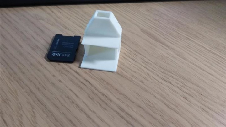
The initial idea was to design the parts using FreeCAD and to print them using a 3D printer so I could fine tune the dimensions before the finished parts are cut from PCB sheet material. I set the sheet thickness to 1.6 mm, which corresponds to a normal PCB. The complete fireplace comprises the following: a back, two side parts, two roof parts, a front, a mantelshelf, and the two sides on which this shelf rests. The nice thing about FreeCAD is that you can easily play around with the dimensions and print the results on a 3D printer to further hone the design. Figure 3 shows the first attempt, which unfortunately turned out to be a bit on the small side for a normal desk, probably more suited to Ken and Barbie’s Alpine chalet.
Figure 3: The initial print next to an SD card for scale.
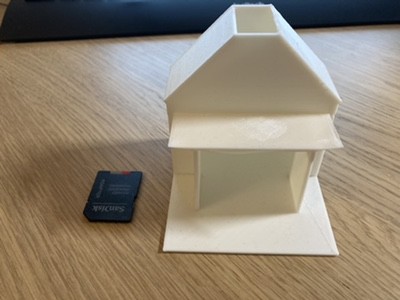
Figure 4 shows a printed version of the basic model, this time using a more suitable proportion.
Figure 4: This version looks about right.
From 3D Model to 2D PCB
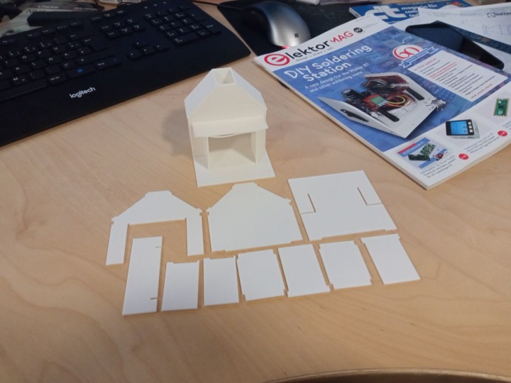
The first step is to print the 3D model as individual parts to check if they will all fit together. Figure 5 shows a few of the components for the chimney held together with adhesive tape. With the model in my hand, I can really explore the structure and see if it is going to work.
Figure 5: The PCB shapes modelled in plastic using a 3D printer.
Thus, a model can be assembled from individual parts with a thickness of 1.6 mm. All parts are created as 3D models in FreeCAD; direct import into KiCad as a PCB is not possible. KiCad can use PCBNEW, the board layout tool, to import board outlines in DXF format, which is what I have done here in this project. From FreeCAD all parts can then be exported as a 2D drawing in DXF format and imported to KiCad again for the board outlines. The fireplace is divided into several KiCad projects, so that I can start work in KiCad.
Simple Circuit, Tricky Component Selection
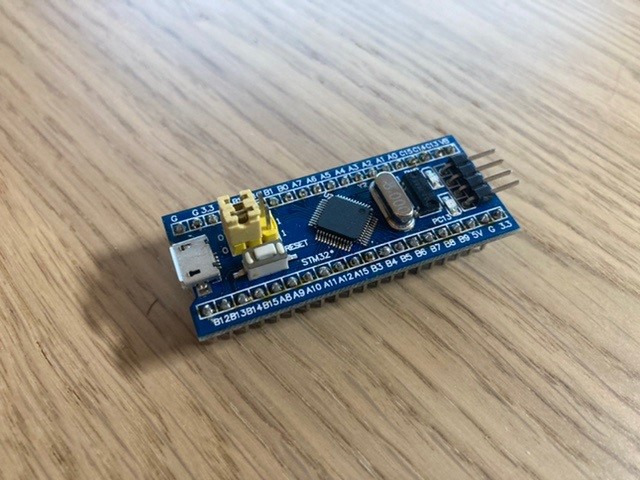
The fireplace generates a flicker flame effect on an LED matrix. This type of circuit has already been covered in a number of books, and it is also used for the Elektor Bedroom Clock. A ULN2308A and 74HCT245 plus series resistors and 64 LEDs together with a simple microcontroller board such as an STM32 BluePill (Figure 6) would do the job.
Figure 6: The STM32 BluePill
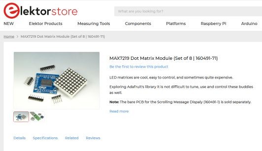
It would also be possible to use a finished LED matrix with a MAX7219, which is available from the Elektor Shop (Figure 7). Unfortunately, these modules were not in stock.
Figure 7: LED matrix on sale from the Elektor Shop.
Component supply is an issue. The availability of boards containing microcontrollers is not as good as it was 24 months ago. Other semiconductors such as the ULN2308A are also temporarily unavailable (or, if they are available, it's at exorbitant prices). That led to a long search in the distributors' online catalogs to find components that are actually in stock and can be delivered before the project deadline and then adapting the circuit diagram to use the components available. What did I end up with? Tracking down the necessary components actually took longer than it did to adapt the circuit and draw it using KiCad.
DIY Christmas Fireplace Circuit
When it’s necessary to switch more than eight LEDs from a single microcontroller, it is best to wire them as a multiplexed matrix array. In our setup, a matrix of 64 LEDs are connected as eight columns and eight rows. The pattern for eight LEDs in a column is sent out while the corresponding column driver is active, after eight such write cycles to each column in the array, the process repeats at a rate so that you do not notice the switching effects. Using this method, we can control 64 LEDs using only 16 GPIOs. (The MAX7219 drives an LED matrix in the same fashion but also has some RAM and brightness control integrated into the IC. New data is sent to the chip via SPI. The chip is, however, way too pricey for this application.)
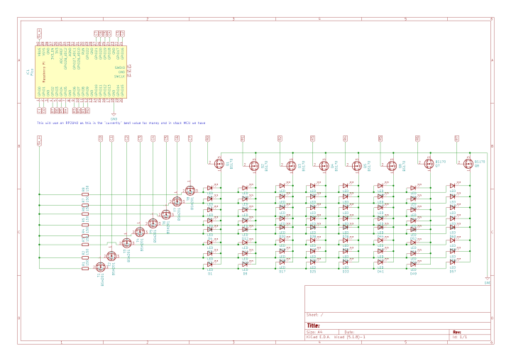
An RP2040 controller on a Raspberry Pi Pico Board is used to control the LEDs. (This board is currently available and is still attractively priced.) 16 FETs are used to switch the power to the LEDs in the rows and columns. These are also used as level shifters. The LEDs take their power directly from the USB port’s 5 V supply so that the Raspberry Pi’s on-board DC/DC converter is not over stressed. Using all the components currently available, we get the circuit shown in Figure 8.
Figure 8: The fireplace circuit diagram.
We now only need to build the circuit as a 3D puzzle. What could possibly go wrong?
Choose a PCB Manufacturer
When putting the boards out for manufacture, it’s important to discuss with the manufacturer your requirements in detail along with your expected turnaround time. If you don’t, you could end up with expensive unusable boards. Check out the location of the production facility to ensure no additional import duties are payable. Delivery times from some EU countries are also not always the shortest.
Since I needed to order components as well as the boards, there were a number of small deliveries that I had to be at home to accept. The boards were created with KiCad, so it was easy to transfer the board file from KiCad directly to the manufacturer, which saves the export as a Gerber data set.
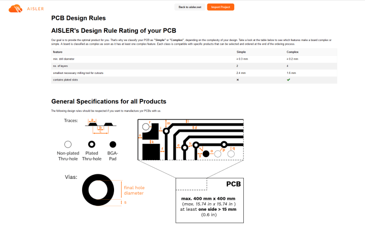
After some investigation I chose our friends at AISLER to produce the boards. They are located within the EU, so I knew delays in customs should not be a problem. AISLER circuit boards are produced in accordance with all the current environmental guidelines, and from 2022, their aim is for the process to be carbon-neutral. They can also supply all the components used on the PCB which is very convenient. All the various design rules that need to be considered for a PCB layout are well documented on the AISLER website (Figure 9).
Figure 9: The PCB specification.
The KiCad board files can be transferred via Drag-and-Drop in the Browser (Figure10).
Figure 10: Upload the files to AISLER via drag and drop.
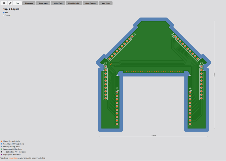
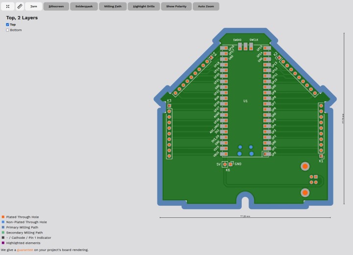
Figure 11: Preview of the PCB by Aisler.net
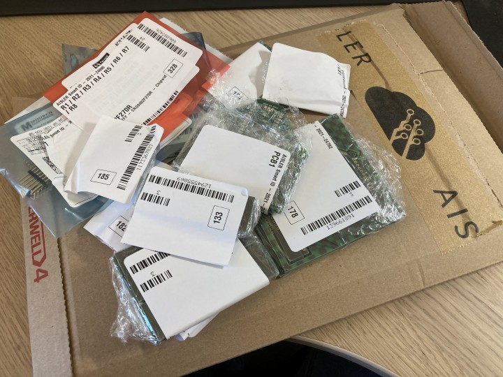
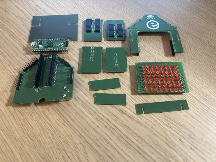
Refer to Figure 11 for a rendering of one of the circuit boards produced by AISLER. The page also provides integrated version control of the uploaded boards. This means you just have to order and wait until all parts arrive in one package (Figure 12). And if you order more than one board, these can be combined into a single package, if you want.
Figure 12: PCBs and components all arrive together.
One or Two Hiccups
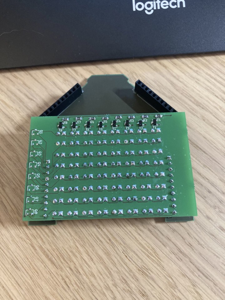
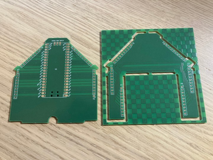
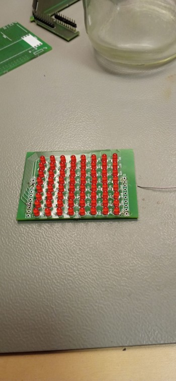
Just as Murphy predicted, if something can go wrong, then you can be sure it will. As with other projects, some things did not necessarily go to plan. In our case, the first hurdle was the 3D assembly. In the first version we put together, it quickly became apparent that the circuit board for the LED matrix (Figure 13) was 2.54 mm too wide on each side. During development, we somehow overlooked the space required for the connectors. If that wasn’t bad enough, the LED matrix circuit board didn’t show any signs of life when we put it through its first tests on the lab bench. That was curious. Double checking the circuit and layout, everything looked good until I noticed that the generic SOT-23 footprint for the BS170 FETs (T1 to T8) assigned by KiCad was incorrect. Doh! Always double check, especially if you haven’t assigned any component pinouts yourself. So far, that’s just two things that could have gone better.
Figure 13: The matrix board is 2.54 mm too wide on both sides.
One important consideration of the PCB production is the method by which the boards are cut out. Milling cutters are used to cut out the board profile. The cutter is not infinitely small so internal corners will not be sharp but have a minimum radius equivalent to the diameter of the milling tool. After uploading the PCB outline information, AISLER shows how it will look after milling. The internal 90º corners are a little more rounded than I had hoped for (Figure 14).
Figure 14: After cutting out, all internal corners will not be sharp.
This aspect had already been taken into account in the PCB design, but unfortunately, the cutouts were still too small. This can be remedied with a file, but that is not the point. The cutouts were adjusted again so that later versions can be put together without a file.
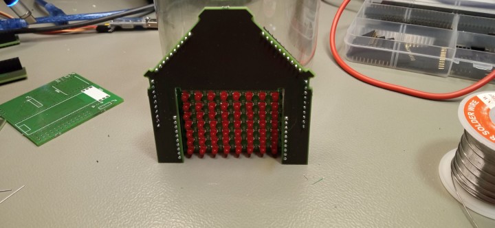
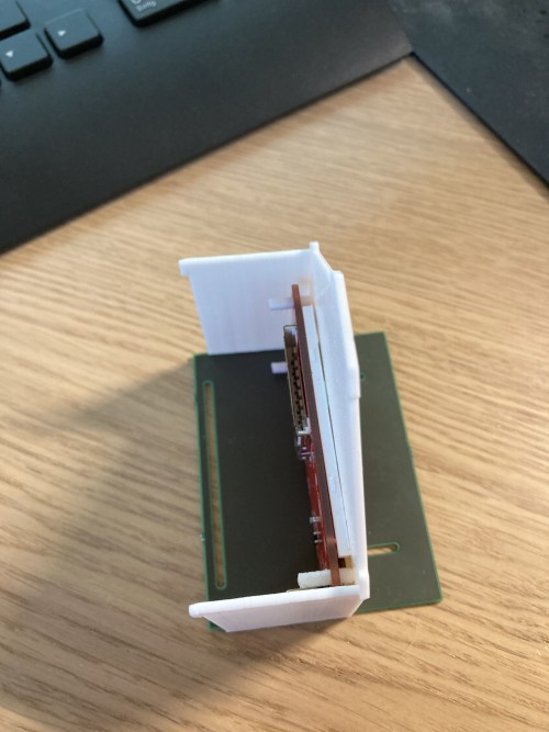
Now for round two, which is to test the express order service offered by AISLER. Two days for PCB production, plus two days for postal transport to your home office (i.e., ordered on Monday morning at 5 AM and delivered on Thursday afternoon). With uncharacteristic foresight I had already ordered components for the second LED matrix board build with the first circuit board. A few components from this circuit board could also still be used to assemble the LED matrix PCB (Figure 15).
Figure 15: The front panel with the matrix PCB fitted.
Virtual Assembly
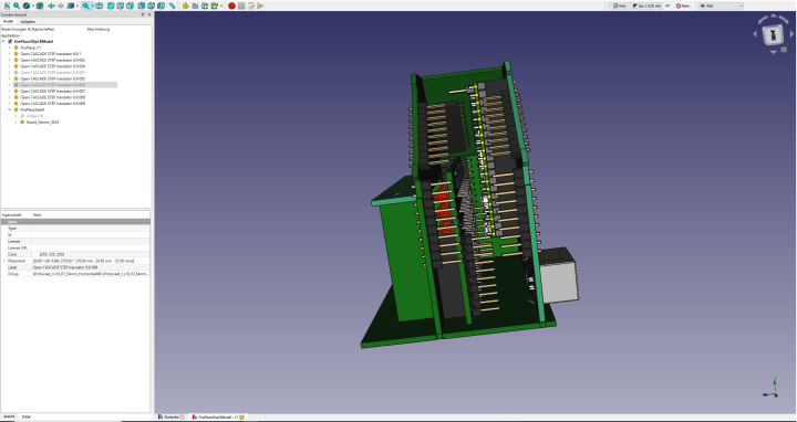
This is where the interaction between FreeCAD and KiCAD is really useful. There is a KiCAD workbench for FreeCAD. This allows PCBs from KiCAD to be imported directly into FreeCAD, with all the 3D models, circuit tracks and labels.
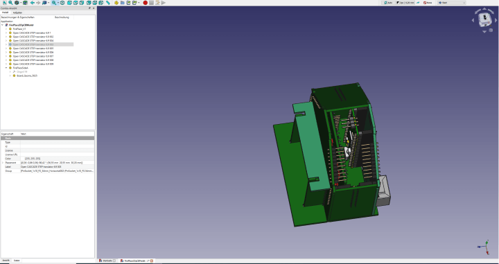
Figure 16:A virtual assembly using the final boards
Figure 17: According to this virtual assembly, everything should fit.
Figure 16 and Figure 17 show all imported boards correctly positioned. The 3D assembly can now be freely rotated in space. Dimensions can also be taken and individual parts can be hidden. In hindsight, I should have gone through this process before ordering the first LED matrix PCB. That would have shown that the board would not fit.
Kaboom?!
It is just one of those sounds you don't want to hear when you power up any circuit for the first time. For me, no smoke signals were released (at least this fireplace design includes a chimney for any smoke to escape) and all the components were still in place.
A quick test of the LED matrix function and the Raspberry Pi Pico on their own showed no problems. In the 3D assembly, signals from the Raspberry Pi Pico are led from the circuit board of the rear wall over the sides and the roof to the front. Each of these boards has been created as a separate KiCad project with its own circuit diagram. The back and side panels had no problems either. Only the front panel had several things that weren't as they should be. Figure 18 shows K1 and K2 on the front board are interchanged. Not only that, the orientation of K1 is rotated by 180º. That’s what comes of not paying enough attention to designing the assembly.
Figure 18: K1 and K2 are swapped.
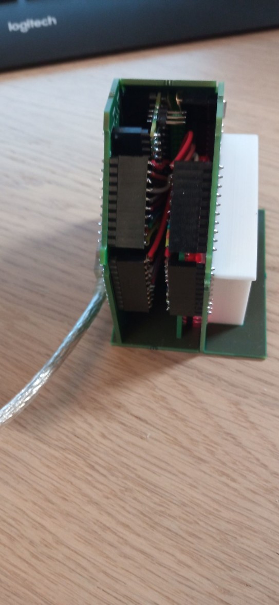
The faulty connections between K1 and K2 are remedied using a few wires so we can carry out a test run of the fireplace (Figure 19).
Figure 19: Flying leads fix the bug
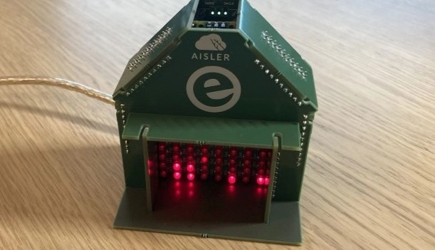
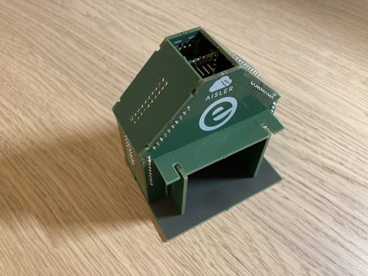
As with the LED matrix, I now had to fix the errors and reorder new boards. The finished structure with the housing made entirely of PCBs can be seen in Figure 20. All that's missing was a hook to hang a Christmas stocking!
Figure 20: The DIY Christmas fireplace built from PCBs.
The Cost of a PCB Structure
If you want to recreate the PCB fireplace, you are welcome to do so, but costs of materials and circuit boards for an assembly this size can quickly exceed €70. My colleagues suggested I could somehow adapt the 3D printed version of the fireplace shown in the November Lab Notes article alongside the PCB variant.
Figure 21: 3D printed variant using a TFT display.
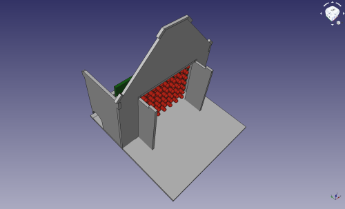
This would seem to be a good solution to reduce costs. The 3D-printed variant (Figure 21) was not designed to accept an LED matrix board. But with a few tweaks to the dimensions using FreeCAD (Figure 22), we can get a virtual impression of how it would all fit together.
Figure 22: 3D printed variant using an LED Matrix.
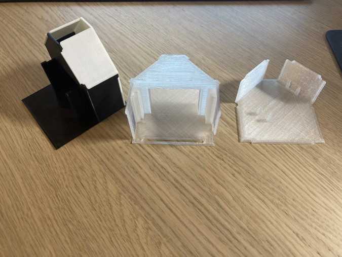
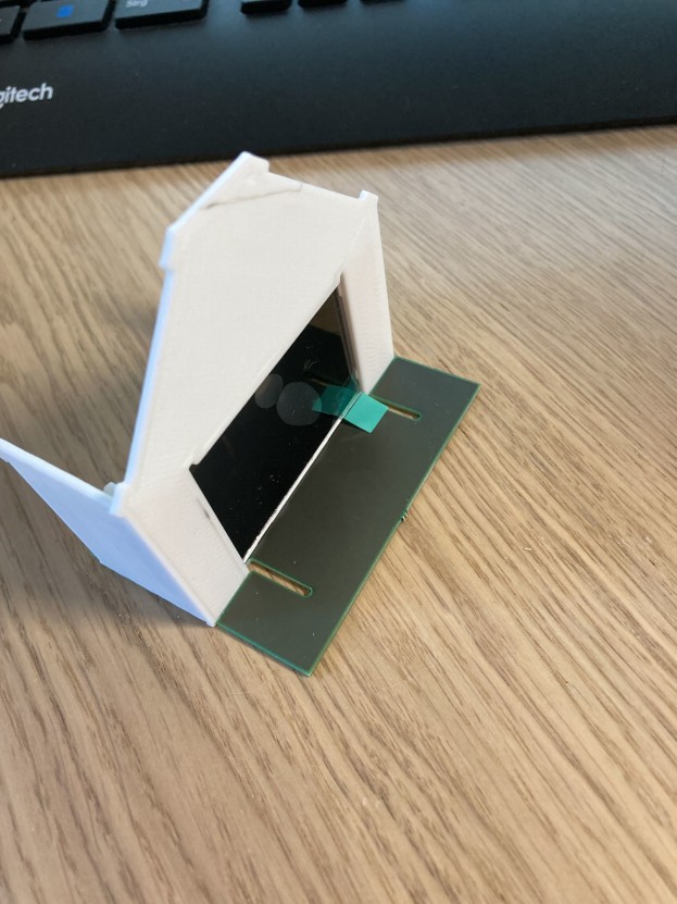
The printed and assembled fireplace (Figure 23) is made up of two printed components (Figure 24). The FreeCAD files and the appropriately exported STEP files for 3D printing are available in the project's GitHub Repository.
Figure 23: A 3D printed version with a PCB mantle piece.
Figure 24: The fireplace is made of two 3D printed components.
The assembly of this variant only requires a Raspberry Pi Pico (which can have pin headers installed), the LED matrix with its components, and a few hookup wires. This variant can be built much more cheaply, especially if you already have a 3D printer on hand. If you are not so equipped, this project may just give you the impetus to start with 3D CAD programming and to get a 3D printer.
The Flame Effect Animation
The fireplace flickering flame animation effect is based on the code written by Code from Mark Kriegsman and the examples given in the FastLED Library with some modifications. The animation is called every 333 ms (three images per second). It calculates a value of "warmth" for each of the LEDs in the 8x8 matrix. The "warmth" values are given one of four possible values of LED brightness and stored in an array.
The multiplex control by the Raspberry Pi Pico is triggered by an interrupt occuring every 8 µs (every 1000 CPU cycles at 125 MHz). The resulting 125-kHz signal is divided between the eight lines of LEDs, so that each line is updated 15,625 times per second. If it were necessary to just switch each LED the control timing used here would be much faster than necessary. The software generates a 7-bit PWM value for each line, so that the 15625 updates per line per second only become 123 per line per second. This allows four different levels of LED brightness to be generated to convey a "flame brightness" effect. Code is available for download from the GitHub rep for this project. For those not familiar with this resource, there is a useful Video made by my colleague Clemens Valens.
Assembling the PCB Version
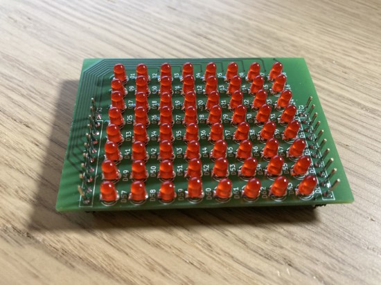
To make the assembly start with the LED matrix (Figure 25) PCB. For this there are 3-mm LEDs and a few SMD components to be fitted. The FETs are in SOT-23 outline while the resistors are in 0805 outline. Try not to be nervous about mounting these components. A set of tweezers will be helpful along with a steady hand.
Figure 25: All components mounted.
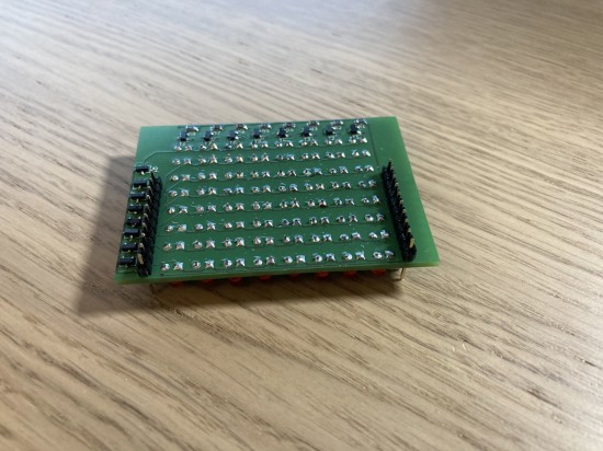
Soldering the 64 LEDs in position can be a bit tedious, just make sure you observe the LED’s polarity. If you fit any the wrong way round, they will not light up later. Space inside the fireplace area is tight so pin headers J2 and J3 are inserted through the circuit board from the rear. The best way to do this is to use pin headers with a pin length of 8 to 8.08 mm measured from the tip to the plastic shoulder (Figure 26 and Figure 27).
Figure 26: Mounting the pin header strips.
Figure 27: Pin headers soldered in position.
With the pin header strips on the matrix PCB the hardest part is now finished. The pin socket strips and the USB socket now can be mounted on the other boards (Figure 28).
Figure 28: All components mounted ready for assembly!
To finish off its just necessary to install the Raspberry Pi Pico with pin headers and load the software. The software is also available as a finished U2F file in the project's GitHub repository.
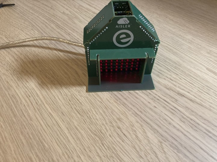
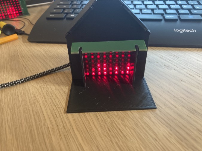
From here on in it's just necessary to plug the side panels, roof, floor, front and rear panel together to create the structure shown in Figure 29. With everything put together correctly, a USB cable can be plugged in to power the unit and the fireplace should flicker into life.
Figure 29: The finished fireplace made from PCB material.
Assembling the 3D-Printed Version
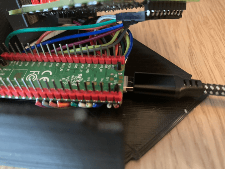
Start off by printing all the parts for this fireplace design. Depending on the speed of your printer this may take over an hour. Once the printing is in process the LED matrix can be fitted with all the components. 90-degree pin header strips can then be used here for locations J2 and J3. Jumper wires are then be soldered directly to the Raspberry Pi Pico and connected appropriately to the LED matrix PCB (Figure 30).
Figure 30: Flying leads connect the Raspberry Pi Pico to the LED array.
And the Variant Using a TFT Display?
The parts for 3D printing and the circuit diagram are more or less finished but the associated software to run on a Raspbberry Pi Pico is not yet ready for release. This means that presentation of this particular variant will be delayed somewhat (Figure 31).
Figure 31: A prototype of the version using a TFT display.
A Finished DIY Christmas Fireplace
This project still has a few rough edges and is not finished, but the result is clearly a cosy flicker flame display, and it demonstrates the process of building 3D structures using PCBs. The interaction between FreeCAD and KiCAD for the construction went really well. With this you are able to visualize how everything goes together before you get to hold the finished article in your hands as a 3D print. Creating this 3D puzzle has been a real education for me beyond the normal challenges of electronics design. Information for the boards and also the 3D construction for FreeCAD can be found for this project on GitHub. My experience with AISLER was very impressive, and its in-house expertise was invaluable. It won’t be the last time I use the services.
The project isn't completely finished, but Christmas is a hard deadline. I now have some time to perfect the design ready for next Christmas. I hope you get the chance to relax over the holiday period, stay safe and healthy!


Discussion (3 comments)