
PIIOX - Raspberry PI-IO-Box
The ultimate Raspberry PI-IO-Box is an open platform for control systems, based on an open BUS including SPI, I2C, digital and analog signals.
The PIIOX system, the ultimate Paspberry PI-IO-Box
The PIIOX (Raspberry PI-IO-Box) is a versatile frame for control and automatic systems. We developed it as test adapter system for testing electronic equipment, but we see that it can do much more than that. It is built upon a versatile bus system that can hold up to 56 modules.
The bus itself is built upon a modular principle. This way the system can stack up to 8 buses together or it can simply just have one bus with 7 modules that easily fits on a desk or in a cap rail system. With 4 BUS that take up to 28 modules a 19’ rack system can be built that has 14 moduls slots oriented to the front and 14 other module slots that take modules from the back. Such a system with 2x7 modules has been used to realize a test system lately.
PIIOX BUS
The bus supplies the modules with power (3.3V, 5V, +/-12V and 24V DC). Further more the bus connects to the module with 3 different bus types: SPI, I2C and parallel 8-Bit interface. It also includes a analogic system that allows +/-10V signals to be converted with a 12 Bit ADC and given out in 12 Bit DAC. The BUS also includes all addressing in the system. It gives 3 addressline for usage within the module in order to simply address 8 devices on the module.
A number of free lines for usage upon need are also given in order to adapt the system to unexpected needs.
For price and compatibility reasons we choose simple pin-header connectors as bus connector.
PIIOX Modules
The design of a new PIIOX module has to be as easy as possible. Two ICs should always be included in each design: an addressing chip (e.g. 4051 or 74’138) and a EEPROM for saving module specific informations. With an additional DG409 a simple 4 differential analog-input is realized. A MIC5891 (SPI relay driver) add 8 relay outputs to a module. Such a module with the 4 ICs has been developed for prototyping.
Quite a handful of different modules have been design already:
In order to debug a module a special extender module has been designed that extands the module 80 mm from the bus; thus allowing to access every part of the module.
The mechanics of a module are also flexible in one direction. First the width of a PIIOX module is 84 mm (print = 80 mm). This allows a system to be built into a 2 HE (88.9mm) 19’ rack system. The overall hight of one module is defined to 25 mm.
The only measure that can be changed would be the length of the module. The standard is 64 mm but is is open and could be increased to 100 mm upon need. However we found the 64 mm (print is 60 mm) a good compromise that also allows the system to be used in cap rail systems. Modules that need more height can use to module spaces so the can be 50 mm of height.
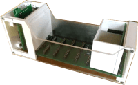
As the system will be an openSource project, it has to be easy to make new modules. Therefor the housing is designed to be printed out on almost any 3D printer. Giving the user many possibilities to use the system in his own ways.
We are currently woring on a system that also allows to completely shield the system according CE regulations. It is obvious that a housing like the one above will never allow a propoer shielding around the electronis. However all forms of housing will be provided as STL and OpenSCAD files.
The following modules have been realized or are planned to be realized within 3 month:
The PIIOX (Raspberry PI-IO-Box) is a versatile frame for control and automatic systems. We developed it as test adapter system for testing electronic equipment, but we see that it can do much more than that. It is built upon a versatile bus system that can hold up to 56 modules.
The bus itself is built upon a modular principle. This way the system can stack up to 8 buses together or it can simply just have one bus with 7 modules that easily fits on a desk or in a cap rail system. With 4 BUS that take up to 28 modules a 19’ rack system can be built that has 14 moduls slots oriented to the front and 14 other module slots that take modules from the back. Such a system with 2x7 modules has been used to realize a test system lately.
PIIOX BUS
The bus supplies the modules with power (3.3V, 5V, +/-12V and 24V DC). Further more the bus connects to the module with 3 different bus types: SPI, I2C and parallel 8-Bit interface. It also includes a analogic system that allows +/-10V signals to be converted with a 12 Bit ADC and given out in 12 Bit DAC. The BUS also includes all addressing in the system. It gives 3 addressline for usage within the module in order to simply address 8 devices on the module.
A number of free lines for usage upon need are also given in order to adapt the system to unexpected needs.
For price and compatibility reasons we choose simple pin-header connectors as bus connector.
PIIOX Modules
The design of a new PIIOX module has to be as easy as possible. Two ICs should always be included in each design: an addressing chip (e.g. 4051 or 74’138) and a EEPROM for saving module specific informations. With an additional DG409 a simple 4 differential analog-input is realized. A MIC5891 (SPI relay driver) add 8 relay outputs to a module. Such a module with the 4 ICs has been developed for prototyping.
Quite a handful of different modules have been design already:
- Analog inputs
- Relais modules,
- step motor controller
- and many more.
In order to debug a module a special extender module has been designed that extands the module 80 mm from the bus; thus allowing to access every part of the module.
The mechanics of a module are also flexible in one direction. First the width of a PIIOX module is 84 mm (print = 80 mm). This allows a system to be built into a 2 HE (88.9mm) 19’ rack system. The overall hight of one module is defined to 25 mm.
The only measure that can be changed would be the length of the module. The standard is 64 mm but is is open and could be increased to 100 mm upon need. However we found the 64 mm (print is 60 mm) a good compromise that also allows the system to be used in cap rail systems. Modules that need more height can use to module spaces so the can be 50 mm of height.
As the system will be an openSource project, it has to be easy to make new modules. Therefor the housing is designed to be printed out on almost any 3D printer. Giving the user many possibilities to use the system in his own ways.
We are currently woring on a system that also allows to completely shield the system according CE regulations. It is obvious that a housing like the one above will never allow a propoer shielding around the electronis. However all forms of housing will be provided as STL and OpenSCAD files.
The following modules have been realized or are planned to be realized within 3 month:
- Relais-Module 8x2x3 (com,nc,no)
- Analog-Inputs 8x2 non isolated
- Analog-Outputs 4x non isolated
- Prototype board including addressing, EEPROM, analog Inputs 4x2, relay driver
- Stepper motor module, based on L6470PD
Want to build a project?
Bring your design to life with the Elektor PCB Service, powered by Eurocircuits. Upload the project files and order professionally manufactured PCBs or assembled boards through a proven European production platform.
Supporting KiCad, Eagle, Gerber, and ODB++ formats, the service is suitable for everything from prototypes and validation builds to series production and volume manufacturing.
Made in Europe. Fast. Reliable. Professional.
Updates van de auteur