A simple timer that indicates if you have slept for at least 8 hours.
Introduction
I could not find a good name for this project. You could also call it an ‘enough sleep timer’. The idea for this project came up during a vacation in winter. We were in a vacation home where there was no alarm clock in the bed room. I normally need 8 hours of sleep but not more than that so when I wake up and I have slept for 8 hours, it is time for me to get out of bed. Unfortunately if you have no alarm clock and it is still dark outside, you need to use your watch or your smart phone - but the latter is not something I keep in my bedroom – to see if you have slept long enough. In order not to have to look at my watch each time I wake up during the night – and need my glasses to read the display – this project was born.
I needed a device that could indicate if I had slept at least 8 hours without the need to be woken up by an alarm clock exactly after 8 hours. They say that the best way to wake up is when your body indicates it, not an alarm clock. The device is a battery powered timer that does the simple thing to blink a LED 8 hours after the device is switched on. So when I wake up I can get out of bed if the LED is blinking and I should catch some extra sleep as long as it doesn’t.
But this is not the only application. If you have small children that cannot yet tell the time yet, you can use this device to let them know they can get out of their bed as soon as the LED starts blinking.
Note that when the LED starts blinking it does not stop until you switch off the device.
As always I built this project around my favorite micro controller the PIC, using the JAL programming language but you can also use an Arduino.
Required components
You need to have the following components for this project:
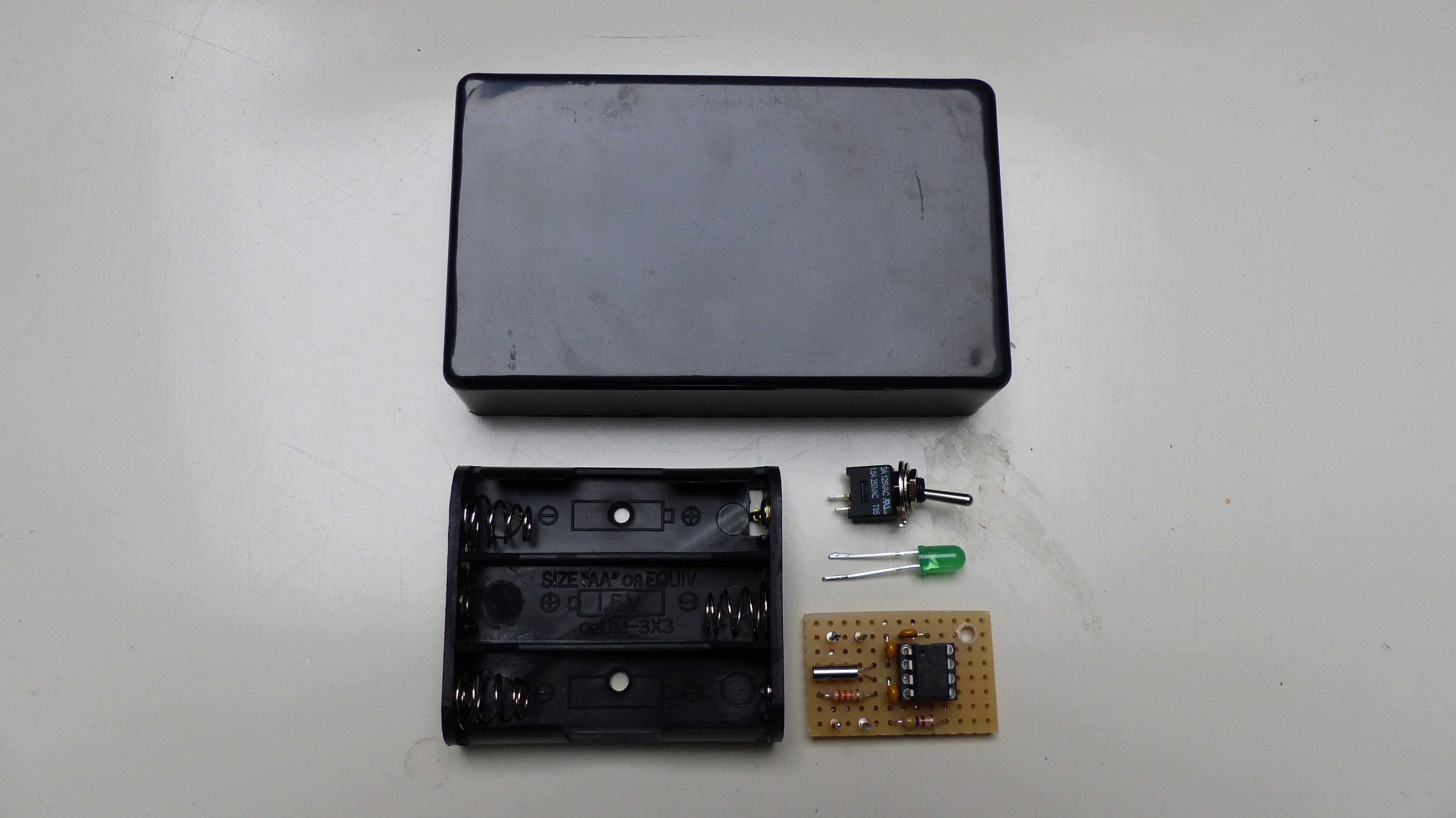
A piece of breadboard
PIC microcontroller 12F615
8-pin IC socket
Watch crystal of 32.768 Hz
Ceramic capacitors: 2 * 22pF, 1 * 100nF
Resistors: 1* 220k, 1 * 33k, 1 * 4k7
Green LED
On/Off switch
Battery holder for 3 AA or 3 AAA batteries + batteries
A plastic housing
See the schematic diagram on how to connect the components.
Designing and building the Electronics
The operating voltage range of the PIC is between 2 Volt and 5.5 Volt which makes it suitable using 3 AA or AAA batteries as power supply. These can be normal batteries (total supply voltage equals 4.5 Volt) or rechargeable batteries (total supply voltage equals 3.6 Volt).
All timing is done in software by the PIC12F615. The main requirement for the design was that the device should be portable and so battery powered. Since the PIC runs at a very low clock frequency of 32 kHz, it consumes around 23 uA at 3.6 V/ 29 uA at 4.5 V when switched on and when the LED is off. This will guarantee a long battery lifetime. Since the LED does not have to be bright, a low current flows through it due to the 4k7 resistor which also contributes to a longer battery lifetime.
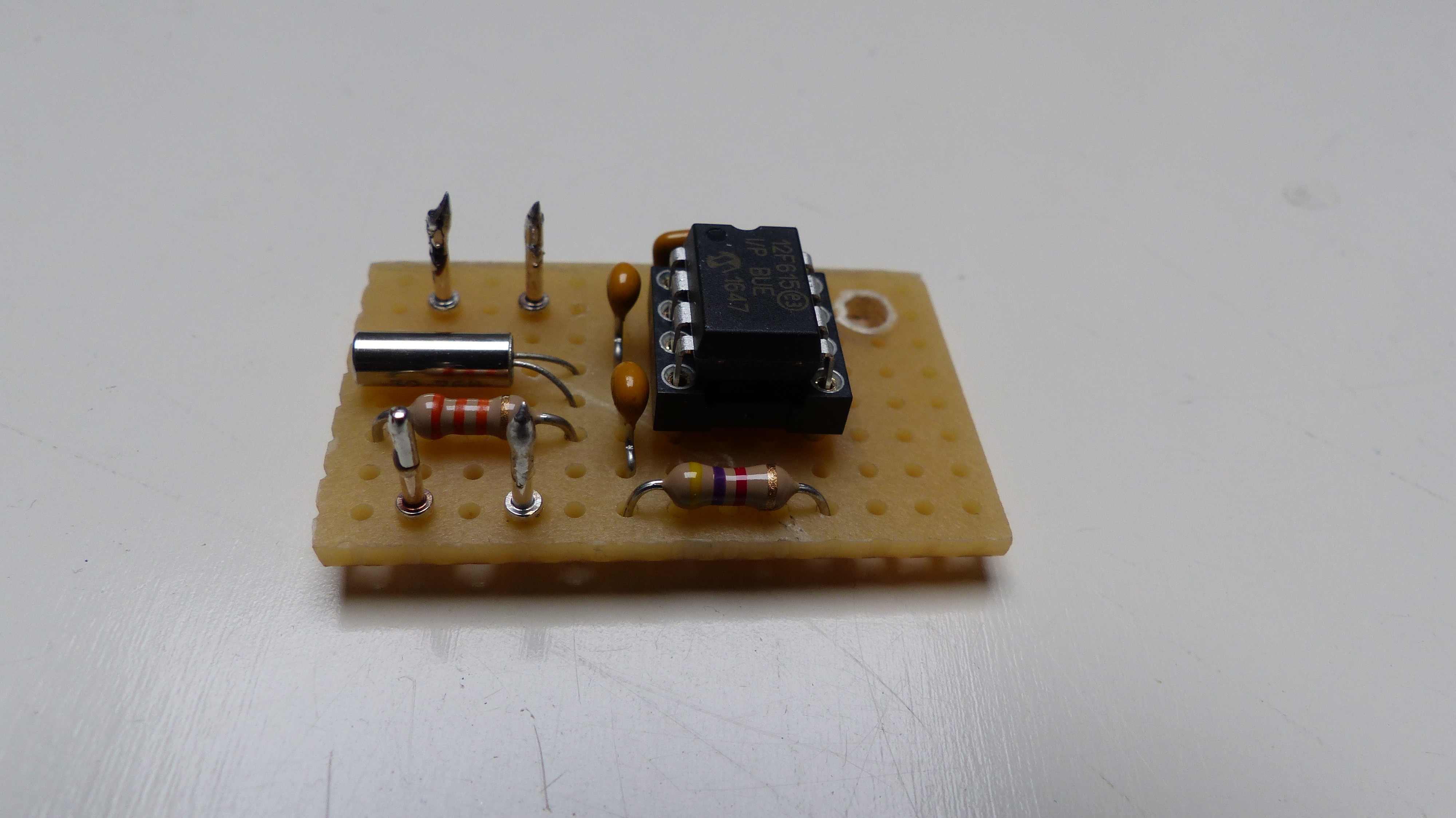
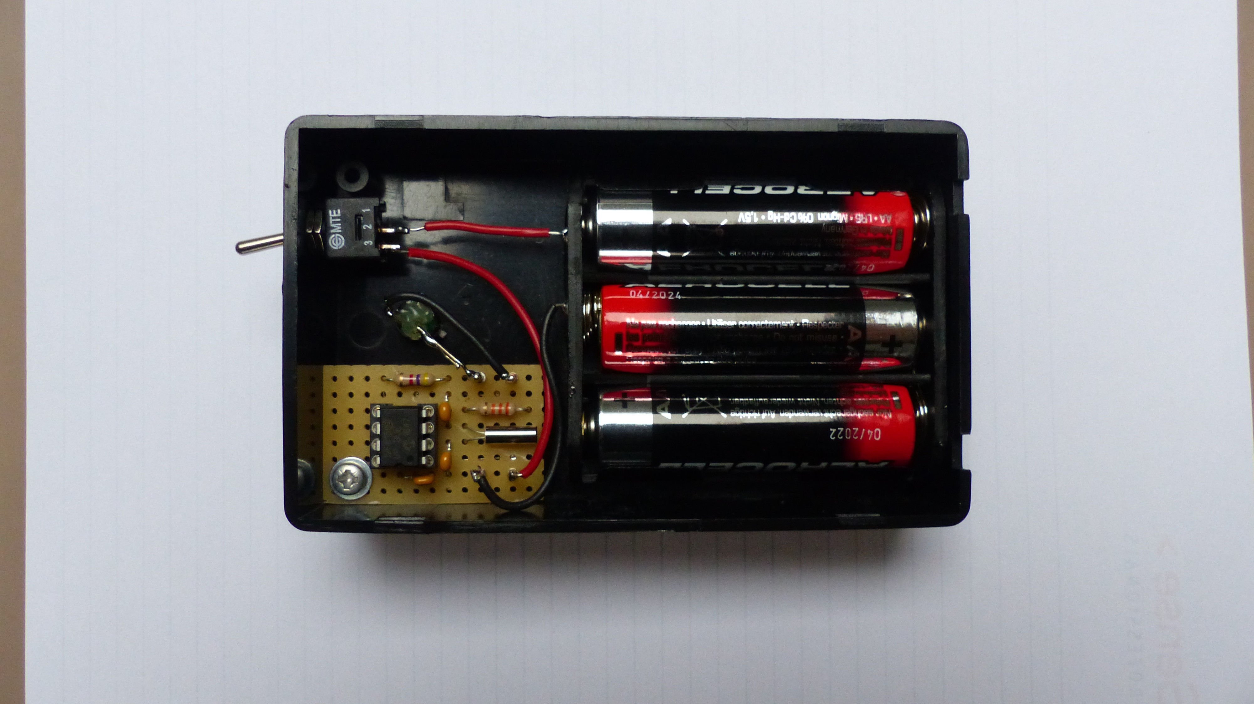
In the pictures you can see the circuit as I built it on the breadboard including the final result when put in a plastic housing. Note that I added a 220k resistor later since the crystal died after some time.
The Software
As already mentioned, the software is written for a PIC12F615 using the JAL programming language. The software performs a simple task. Using a timer of the PIC, the clock crystal clock of 32.768 Hz is divided by 32.768, resulting in an internal signal of 1 second. The PIC then uses a counter to count from 0 until 60 seconds * 60 minutes * 8 hours = 28.800.
When the device is powered on, the LED will blink 3 times, after which the 8 hour timer starts. Blinking at power on is done to show that there is still sufficient power in the batteries. After 8 hours the LED will start blinking again but will only stop blinking when the device is switched off.
There is one additional feature in the device. Rechargeable batteries should not be discharged completely. To prevent that, the device will check the battery voltage once when switched on. If the battery voltage is below 3.0 Volt, the device will not blink the LED and will go into sleep mode. The device needs to be switched off and the batteries need to be replaced after which it will function normally after it is switched on again.
The JAL source file and the Intel Hex file for programming the PIC are attached. If you are interested in using the PIC microcontroller with JAL – a Pascal like programming language – visit the JAL website.
Have fun building your own project and looking forward to your reactions and alternative applications.
Want to build a project?
Bring your design to life with the Elektor PCB Service, powered by Eurocircuits. Upload the project files and order professionally manufactured PCBs or assembled boards through a proven European production platform.
Supporting KiCad, Eagle, Gerber, and ODB++ formats, the service is suitable for everything from prototypes and validation builds to series production and volume manufacturing.



Discussie (0 opmerking(en))