
Adjustable Electronic Load
This is a simple Adjustable Electronic Load using a LM317 and a MOSFET. It's ajusted with a potentiometer.
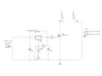
The principle of this adjustable electronic load circuit is quite simple. It is a matter of controlling the resistance on (Ron) of a MOSFET by setting its voltage VGS by means of an adjustable voltage regulator.
I used an LM317T to apply the variable voltage on VGS of an IRFP240.
Between the drain and source pins of the MOSFET are inserted in serie an ammeter and the power supply to be tested. It is also necessary to place a voltmeter in parallel on the power supply to measure the voltage drop according to the current supplied, see photo.
The MOSFET is placed on a heatsink that could be ventilated if the current to be tested is too high.
An adjustable resistor is inserted in series with the potentiometer to set the minimum voltage to be applied to the MOSFET for it to conducts.
The test is started by setting the voltage adjusting potentiometer to the minimum and turning it very gradually in order to give time to the MOSFET to dissipate the induced heat.
The characteristics of the power supply are read on the ammeter and voltmeter connected.
The VDS and ID characteristics of the MOSFET must be greater than the voltage and current values of the power supply to be tested. To measure very high current and better dissipate the heat one can put several MOSFET in parallel.
This circuit is intentionally simple, but it is possible to replace the potentiometer by a microcontroller which switches various resistors in order to test the load dynamically.
In fact, I first used this circuit this way, since I created it to serve as a current source to my class A single ended amp, on which I switch 3 different resistors to adjust the amp on 5, 10 or 20 watts max. I mostly only use 5 watts and in this period of respect for the environment it is a shame to "waste" all the energy of the 20 w class A amp (200 w total) to use only 5.
Want to build a project?
Bring your design to life with the Elektor PCB Service, powered by Eurocircuits. Upload the project files and order professionally manufactured PCBs or assembled boards through a proven European production platform.
Supporting KiCad, Eagle, Gerber, and ODB++ formats, the service is suitable for everything from prototypes and validation builds to series production and volume manufacturing.
Made in Europe. Fast. Reliable. Professional.
Discussie (0 opmerking(en))