
Display multiple sensor values on an LCD with an attiny85
Use an ATtiny85 to display sensor values on an I2C LCD (equiped with PCF8574): GY21P (Si7021+SHT21) I2C sensor, temperature and relative humidity DS18b20 Dallas sensor, one wire, temperature
I had tried to use an ATtiny85 and a 2X16_I2C LCD, but the compilation revealed a multitude of warnings.
I'm not a fan of warning, so I left the idea on hold.
The need for simple and mobile temperature/humidity measurement and display challenged me.
I started by reviewing the LiquidCrystal_ATtiny library and validated the _revBC version
A first test code uploaded to the Attiny is satisfactory.
TEST_I2C_LCD_ATtiny85
it is a simple counter up to 1000, displayed on the LCD, which confirms correct operation.
I carried out a second step, adding a shield sensor GY21P (Si7021+SHT21) which returns temperature and humidity.
NOTE::
the GY21P shield is powered by 5V!!
A voltage regulator type XC6206 (662K_reg3V3) is on board. (see data sheet)
Some functions from the Si7021 library have been adapted and installed in the code.
TEST_I2C_Si7021_LCD_ATtiny85_v2
The satisfactory results, remaining a few usable pins on the ATtiny,
I added a DS18B20 sensor with an identical reading to the ATtiny_Fan mount
see Lab : Variateur for 12V ventilator or Fan
The code uses the ISR WDT Watch Dog to count and validate the measurement reading
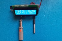
We interrogate the GY21P which returns temperature and humidity, then the Dallas Ds18B20 sensor.
The measures values are displayed.
TEST_I2C_DS18B20_Si7021_LCD_ATtiny85_v2
You can use and modify these three codes or all codes at your convenience.
short video here :
Only Si7021
https://youtu.be/FP8w9qeFBvM
SI7021 and DS18B20
https://youtu.be/dF9ZkFui-zM
///FR
Utiliser un ATtiny85 pour afficher sur un LCD I2C les valeurs de capteurs :
GY21P (Si7021+SHT21) capteur I2C, température et humidité relative
DS18b20 capteur Dallas, One wire, température
J'avais tenté d'utiliser un ATtiny85 et un LCD 2X16_I2C, mais la compilation laissait apparaître une multitude de warning.
Je ne suis pas un fan de warning, aussi j'ai laissé l'idée en pause.
Le besoin de mesure et affichage de température/humidité simple et mobile m'a remis à l'épreuve.
J'ai commencé par revoir la librairie LiquidCrystal_ATtiny et validé la version _revBC
Un premier code de test téléversé dans l'Attiny donne satisfaction.
TEST_I2C_LCD_ATtiny85
C'est un simple compteur jusqu'à 1000, affiché sur le LCD, qui confirme le bon fonctionnement.
J'ai réalisé une deuxième étape, ajouter un capteur shield GY21P (Si7021+SHT21) qui retourne température et humidité.
NOTA ::
le shield GY21P s'alimente en 5V !!
Un régulateur de tension type XC6206 (662K_reg3V3) y est embarqué.(voir data sheet)
Quelques fonctions issues de la librairie Si7021 on été adaptées et installées dans le code.
TEST_I2C_Si7021_LCD_ATtiny85_v2
Les résultats donnant satisfaction, restant quelques pins utilisables sur l'ATtiny,
j'ai ajouté un capteur DS18B20 avec une lecture identique au montage ATtiny_Fan
voir Lab : Variateur for 12V ventilator or Fan
Le code utilise les ISR WDT Watch Dog pour compter et valider le relevé de mesures
On interroge le GY21P qui retourne température et humidité, puis le capteur dallas Ds18B20.
On affiche les valeurs de mesures.
TEST_I2C_DS18B20_Si7021_LCD_ATtiny85_v2
Vous pouvez utiliser et modifier à votre convenance un des trois code... ou les trois !
short vidéo ici :
Si7021 seulement
https://youtu.be/FP8w9qeFBvM
SI7021et DS18B20
https://youtu.be/dF9ZkFui-zM
I'm not a fan of warning, so I left the idea on hold.
The need for simple and mobile temperature/humidity measurement and display challenged me.
I started by reviewing the LiquidCrystal_ATtiny library and validated the _revBC version
A first test code uploaded to the Attiny is satisfactory.
TEST_I2C_LCD_ATtiny85
it is a simple counter up to 1000, displayed on the LCD, which confirms correct operation.
I carried out a second step, adding a shield sensor GY21P (Si7021+SHT21) which returns temperature and humidity.
NOTE::
the GY21P shield is powered by 5V!!
A voltage regulator type XC6206 (662K_reg3V3) is on board. (see data sheet)
Some functions from the Si7021 library have been adapted and installed in the code.
TEST_I2C_Si7021_LCD_ATtiny85_v2
The satisfactory results, remaining a few usable pins on the ATtiny,
I added a DS18B20 sensor with an identical reading to the ATtiny_Fan mount
see Lab : Variateur for 12V ventilator or Fan
The code uses the ISR WDT Watch Dog to count and validate the measurement reading
We interrogate the GY21P which returns temperature and humidity, then the Dallas Ds18B20 sensor.
The measures values are displayed.
TEST_I2C_DS18B20_Si7021_LCD_ATtiny85_v2
You can use and modify these three codes or all codes at your convenience.
short video here :
Only Si7021
https://youtu.be/FP8w9qeFBvM
SI7021 and DS18B20
https://youtu.be/dF9ZkFui-zM
///FR
Utiliser un ATtiny85 pour afficher sur un LCD I2C les valeurs de capteurs :
GY21P (Si7021+SHT21) capteur I2C, température et humidité relative
DS18b20 capteur Dallas, One wire, température
J'avais tenté d'utiliser un ATtiny85 et un LCD 2X16_I2C, mais la compilation laissait apparaître une multitude de warning.
Je ne suis pas un fan de warning, aussi j'ai laissé l'idée en pause.
Le besoin de mesure et affichage de température/humidité simple et mobile m'a remis à l'épreuve.
J'ai commencé par revoir la librairie LiquidCrystal_ATtiny et validé la version _revBC
Un premier code de test téléversé dans l'Attiny donne satisfaction.
TEST_I2C_LCD_ATtiny85
C'est un simple compteur jusqu'à 1000, affiché sur le LCD, qui confirme le bon fonctionnement.
J'ai réalisé une deuxième étape, ajouter un capteur shield GY21P (Si7021+SHT21) qui retourne température et humidité.
NOTA ::
le shield GY21P s'alimente en 5V !!
Un régulateur de tension type XC6206 (662K_reg3V3) y est embarqué.(voir data sheet)
Quelques fonctions issues de la librairie Si7021 on été adaptées et installées dans le code.
TEST_I2C_Si7021_LCD_ATtiny85_v2
Les résultats donnant satisfaction, restant quelques pins utilisables sur l'ATtiny,
j'ai ajouté un capteur DS18B20 avec une lecture identique au montage ATtiny_Fan
voir Lab : Variateur for 12V ventilator or Fan
Le code utilise les ISR WDT Watch Dog pour compter et valider le relevé de mesures
On interroge le GY21P qui retourne température et humidité, puis le capteur dallas Ds18B20.
On affiche les valeurs de mesures.
TEST_I2C_DS18B20_Si7021_LCD_ATtiny85_v2
Vous pouvez utiliser et modifier à votre convenance un des trois code... ou les trois !
short vidéo ici :
Si7021 seulement
https://youtu.be/FP8w9qeFBvM
SI7021et DS18B20
https://youtu.be/dF9ZkFui-zM
Updates van de auteur