
Idealer RC Kreuzmischer für Kettenfahrzeuge, Schiffe m.2 Schrauben, Roboter
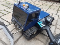
RC Cross mixer for tracked vehicles, ships with two propellers, robots without the usual drawbacks. Basic Arduino MC with 328 processor (e.g. Nano)
Of course you can drive these vehicles conventionally with two joysticks (one for each drive side).
But if you want to work with a pistol grip system or with XY joystick you need a mixer of both information,
Forward/Backward (THR) and Left/Right (STR), proportionally calculated and processed accordingly, passed on to the two motor controllers.
Servos and motor controllers are controlled with variable pulses in the range from 1000µs to 2000µs with approx. 50Hz.
Simple adding or subtracting is not possible because the maximum value would be exceeded if the steering angle was full and a little bit more.
Zero position 1500µs
THR 2000µs
STR 1700µs
zero position + 500 (THR zero position) + 200 (STR zero position) =2200µs !!!!>2000µs
The safest and simplest method is to halve both values and then add. This ensures that the limit value is never exceeded.
will be.
Disadvantage: Only max. 50% speed and steering angle can be achieved!
Here it is solved better..both values are added, then a factor is used as ratio of the output value to the maximum value (plus and minus).
is calculated. If this is greater than 1 or less than -1, both output values are divided and only then output.
So you can drive with maximum speed and turn with maximum speed on the spot.
The time measurement of the two signals (THR and STR) from the receiver is interrupt controlled and a flag is set each time the signal
was read/measured again. If there are two new measured values, the calculation is carried out and the signals are output to the controllers.
The system is thus latency-free and works synchronously with the update rate of the remote control.
In addition, a speed-dependent "steering damping" can be switched on or off by jumper.
The higher the speed, the smaller the steering signal will be, so that there is no chain at full speed and sudden full deflection of the steering.
Setup:
The system contains a serial output option for the pulse lengths (High and Low), the correction factor and the output values.
Since this is unnecessary in normal operation, it is always deactivated at startup, but can be changed by sending a single character (no matter which one).
can be activated. Interface parameters: 115200,8,N,1
This sets THR and STR to approx. 1500µs high time (trimming) without connected motors.
Then calibrate the controllers (see Manuall Controller).
Connect motors... ready
The maximum values are contained in the source code as variables and can be adjusted if necessary.
Updates van de auteur