Incorrect circuit discovered?
In my 0-50V 2A Variable DC bench power supply (Refresh) LAB, Someone commented that the current limiting part of the circuit was incorrect. This circuit had been working faultlessly for forty-years so I trusted it. However, I thought that I should take these comments seriously and this project is an open invitation to Elektor readers to add there own comments to the investigation.
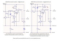
This is a suggested circuit revision for the current control circuit of the Variable 0-50 Volt 2 Amp dc bench supply (Refresh). as compared to the Elektor original.
Please give your comments regarding the two designs.
This exercise is a theoretical investigation in to a reportedly broken circuit! previously published in Elektor 1980 in conjunction with the Texas Instruments LM10 Design Notes.
Discussie (4 opmerking(en))
Ulrich Dreher 2 jaar geleden
At that time transistors were expensive enough to not waste a single one. From this excerpt of the whole circuit Q2 may look wrong, considering the full circuit Q1 (driven by U1) does what the critic wants to be done by Q2.
N.B.: without knowledge of the complete circuit it is difficult to "improve" such.
Reference: https://www.ti.com/lit/ds/symlink/lm10.pdf - Figure 48
Roel Arits 2 jaar geleden
I overlooked a connection that shouldn't be there in the schematic between the LM10 OPAMP and Q2.
Nevertheless the current limiting will work with or without this connection, so you don't notice it when using the power supply.
This wrong connection makes Q2 superfluous and causes the OPAMP to do the work directly.
That is why you don't notice this problem.
In the attachment i added a picture of the connection that should not be there.
Sorry for having overlooked this.
Best regards,
Roel
Roel Arits 2 jaar geleden
You wrote:
"No steady direct current can pass through R5.
Therefore, Q2 base/emitter junction cannot conduct."
R5 is in fact just a kind of pull up that keeps T2 cut off as long as IC2 didn't detect that the set current limit is exceeded. At the moment the current limit is exceeded, the output of IC2 will go low. When the output goes low, it will pull current through D2 and through the base-emitter junction of T2. In other words: the low IC2 output will make T2 conduct. T2 will squeeze the voltage at the base of T4 down (and thus the output voltage) until the current is again below or equal to the set current limit.
The confusing part might be that T2 is shunting down it's supply voltage (which is also the supply voltage of the OPAMP) simultaneously with squeezing down the voltage at the base of T4.
I guess the idea is to get a better voltage and current regulation. I can imagine that it improves the stability and response time to output load variations.
Best regards,
Roel.
Roel Arits 2 jaar geleden
There is nothing wrong with the current limiter of the 1980's power supply design. It will work perfectly.
It is a bit of an unusual design which will only work because of the special features of the LM10 OPAMP/voltage reference. The special feature is that the LM10 can work with power supplies down to 1.2V.
The internal voltage reference of 0.2V will also be happy with power supply voltages down to 1.2V.
This characteristic is used in the design of both the voltage regulation and the current limiter, because they
both individually shunt the power supply for the respective LM10's and this way regulate the base voltage of T4.
This base voltage is regulated down to 2.1V when either the current limiter is maximal squeezing down the output voltage to 0 or when the output voltage is manually adjusted down to 0 with the voltage potmeter.
In the attached picture i tried to explain why this design is perfectly fine.
Best regards,
Roel.