
Multiplexing is fun on Raspberry Pi
I2C – the extension of GPIOsThe Raspberry Pi has 26 ports out of w
- I2C – the extension of GPIOs
The Raspberry Pi has 26 ports out of which a handful GPIOs left to do great works. But to further impress your neighbor with your fancy Raspberry Pi here's how you can connect additional micro controllers to extend the GPIOs capability by any numbers !
Even the clumsy LCD panel which has eaten away half a dozen of GPIOs can straight away be shifted to the additional micro controllers leaving the Raspberry Pi with only 2 wires to control all these countless GPIOs precisely yet very economically.
The new mantra is I2C , just two wires - SDA and SCL (Pin-3 & Pin-5) will control all these additional devices. The small help that I've borrowed from Adfruit.com is in the form of a GPL python script to manage these extended GPIOs.
System set up: To use I2C on Raspi you need to enable a few things in Wheezy Raspbian as by default it is not enabled. This is a fairly easy process. First you need to edit the modules file using :
$ sudo nano /etc/modules
#and add the following two lines
i2c-bcm2708
i2c-dev
Save the file and exit nano and open the next file
$ sudo nano /etc/modprobe.d/raspi-blacklist.conf
Put a # symbol at the beginning of the two lines so that they look like this:
#blacklist spi-bcm2708
#blacklist i2c-bcm2708
save and exit nano.
Now install the necessary softwares to manipulate the I2C bus. Assuming your Raspberry Pi is connected to Internet, issue the following commands at a shell prompt.
$ sudo apt-get update #this updates your Raspberry Pi
$ sudo apt-get install python-smbus i2c-tools #instals smbus & i2c tools
So far so good. Relax now ! As the next step is going to be little messy but be rest assured that soon you will have enough knowledge to expand your Raspi with as high as 8 – 16 – 64 or whatever you like no of GPIOs and then controlling these extended GPIOs by only two wires from your Raspi !
Once the softwares are installed reboot your Raspi so that these effects take place permanently.
$ sudo reboot
However, my nephew likes to use the Raspi like a TV and he simply switches it off and then switches on and it works glitch free !
Connections: Two package MCP23008 ( 18 pins DIL ) and MCP23017 (28 pin DIL) is taken for our exercise. Together they comes for around Rs:200 ($3.4 from element14.com ) from kit's n spares. Connect them as shown in the figure-2
Testing: Once you have connected the hardware double check the wiring. Make sure the 5 volt is going to the correct pins else it will heat up the microprocessor and damage it eventually. Also ensure the reset pins (6 or 18 ) are connected with the +5V rail. Open a shell prompt from a remote connection or from the local and issue the following command.
$ sudo i2cdetect -y 0 or $ sudo i2cdetect -y 1
If your Raspi is version 1 then use 0 else 1 and watch for the following screen appears at the terminal prompt. See detail of the output of this command in figure-1.jpg
[figure-1.jpg]
Congratulations ! Pat your back , your cute Raspi has successfully detected the hardware at 0x20 address. Now it's only a matter of time to issue commands to control it. The address is 0×20 because all the three address pins (A0,A1,A2 ) are set low. If you set only A0 high (connected to +5 volt) & A1 & A2 are low, the address would have become 0×21.
This signifies one fundamental issue with the I2C communications - You can connect any number of devices on the I2C bus (Pin-3 & Pin-5) but all devices should have a unique address. So how you set A0, A1 and A2 is going to define different address for the different devices. You may try that feats here to gain more confidences now.
Testing: There is a command line testing for I2C on Raspi. Connect a few LEDs on the pins as shown in figure-2 and issue the following commands.
$sudo i2cset 0x20 0x00 0x00 #this will switch on the LED on A0 $ sudo i2cset 0x20 0x00 0x01 #this will switch off the LED on A0
The command line program is easy ,provided you understand the binary and hex conversion of all the numbers, bits and not talk of the impressive datasheet that comes with each micro processors. However, Adafruit.com has an excellent library by which we can manipulate these GPIOs in a far more lucid way.
Open a terminal window and write the following python scripts. However, all the program files including the Adafruit library is provided in the source location. Download it and then expand them all in a fixed location.
$sudo nano mcp23017.py
Err INCLUDE_FULL type: template not found.
Run the program at the command prompt by
$sudo python mcp23017.py
You will find the LEDs will change in sequence continuously. The pin-4 is set as input and it's internally made 1 by it's pull up resistor. Join it with the ground and you will see the print out changes from 1 to 0.
Author's Prototype is here :
[figure-5.jpg]
The same feats can be achieved with the MCP23008 too but because it has only 8 GPIOs therefore, the no of outputs to be reduced to 0 to 7 unlike 0 to 15 for MCP23017. Also if we connect a number of MCP23017 or a combination of MCP23008 then for each to have a different address we have to make different combinations of the Address pins (A0,A1,A2) and accordingly in the instance of the Adafruit library we have to change the address bits.
mcp1 = Adafruit_MCP230XX(address = 0x20, num_gpios = 16) # MCP23017 mcp2 = Adafruit_MCP230XX(address = 0x21, num_gpios = 8) # MCP23008 mcp3 = Adafruit_MCP230XX(address = 0x22, num_gpios = 16) # MCP23017
----- like that we have to change in our program --------
LCD Panel on extended GPIOs: Now lets do something more interesting on the extended GPIOs. We will make our MCP23008 to drive a 4*16 common Hitachi LCD panel with a few real time data. Refer to figure-4 more more connection detail.
Connections:Wire up the LCD panel like this : [ refer figure-4 ]
LCD Pin | Function | Pi Pin | MCP23008 Pin |
01 | GND | PI-6 | - |
02 | +5V | PI-2 | - |
03 | Contrast via 5K pot : center | PI-6 PI-2 | - |
04 | RS | - | 0 |
05 | RW | PI-6 | - |
06 | Enable | - | 1 |
07 | Data 0 | N/C | - |
08 | Data 1 | N/C | - |
09 | Data 2 | N/C | - |
10 | Data 3 | N/C | - |
11 | Data 4 | - | 2 |
12 | Data 5 | - | 3 |
13 | Data 6 | - | 4 |
14 | Data 7 | - | 5 |
15 | +5V via 560ohm resistor | PI-2 | - |
16 | GND | PI-6 | - |
Hook up the DS18B20 temperature sensor like this.
[figure-6]
GPIO4 is Raspi physical Pin 7. The DS18B20, the temperature scanner is connected to the Raspi GPIO4 which is physical pin no 7 while the LCD panel is connected on the MCP23008. Apart from Gnd & 5 volt only two more wires – SDA,SCL have gone to the MCP23008 board.
Softwares:
Adafruit_MCP230xx.py and Adafruit_I2C.py - these two GPL libraries are taken from Adafruit.com . They can be downloaded using github alternatively they are included in the source here. The other two files lcd23008.py and iptalk2mcp.py are for running the 16*4 LCD panel and the date / time / Day / temperature clock. Download the link, extract all 4 files in a directory and then run iptalk2mcp.py.
[Files included in the source directory]
$sudo python iptalk2mcp.py
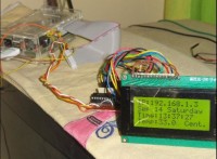
The LCD as connected on the MCP23008 will start showing the IP Address, Day , Date and time along with ambient temperature. In case the Raspi does not have any IP address then the IP address portion will remain blank.
The files are also all available in zip format here
To make it running every time it boots , add the above line some inside the /etc/rc.local file before the exit command.
$> sudo nano /etc/rc.local
[add somewhere before the exit line]
sudo python /home/pi/iptalk2mcp.py &
Bye bye,
S. Bera
Want to build a project?
Bring your design to life with the Elektor PCB Service, powered by Eurocircuits. Upload the project files and order professionally manufactured PCBs or assembled boards through a proven European production platform.
Supporting KiCad, Eagle, Gerber, and ODB++ formats, the service is suitable for everything from prototypes and validation builds to series production and volume manufacturing.
Made in Europe. Fast. Reliable. Professional.
Discussie (0 opmerking(en))