
Rapid Development Board for Raspberry PICO
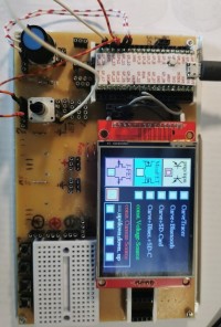
In some of my projects, I use the Raspberry PICO (RP2040 or RP2350) with the TFT_SPI color display ILI9341 or ILI9488 / ST7735. They are cheap, and are available with Touch-Screen and SD-Card Slot. With the lib arduino-pico from Earlephllhower it's possible to use the ARDUINO IDE, Together with the great grafic library: tft_esp32 from Bodmer it's easy to develop also bigger projects on the development board. You have only to put the display in the sockets (2.4" to 4").
- socket for the PICO RP2040 / RP2350 board
- sockets for TFT-SPI-Displays (2.4, 2.8, 3.2" ILI9341 and 3.5, 4.0" ILI9488)
- socket for EEPROM 24LC64/265
- socket for Dual-DAC MCP4802 / MCP4812 / MCP4822
- socket for Quad-ADC MCP3004 / MCP3204 with voltage divider
- 2 sockets for Servos
- 4 sockets for rotary encoder and/or Potentiometer
- Mini bread-board (17x10 pins)
- 1 reset-button
- 4 switch-buttons
- 4 sockets for LEDs
- ext. power-supply over USBC
- positive voltage +12V (max 1.5A )
- positive voltage +5V (max 700mA)
- negative voltage -5V (max 150mA)
-
- sockets for +, ground ,-
- sockets for SPI and I2C
new:
Arduino-NANO Adapter with divider 5V/ 3.3V (testet with Nano 328P/328BP)
Arduino-NANO Adapter without divider for 3.3V NANOs ( tested with ESP32-S3-Nano)
The display(s) and the DACs are fixed wired to SPI-0 : SPIO16=MISO,GPIO17=TFT_CS,GPIO18=SCK,GPIO19=MOSI, (DAC_CS not connected)
The SPI-Pins for ADCs and the SD-Card are not connected, SPI-Pins on connectors.
In the next weeks ? I will show here some projects I have realized with (help of) the development board.
on github new/ changed KiCad (9.01) layout and schematics also from the adapters.
A video from fixing the 5V-Nano-adapter on the Pico-Board on Youtube::
https://www.youtube.com/shorts/ZtuZCsJPJG8
Want to build a project?
Bring your design to life with the Elektor PCB Service, powered by Eurocircuits. Upload the project files and order professionally manufactured PCBs or assembled boards through a proven European production platform.
Supporting KiCad, Eagle, Gerber, and ODB++ formats, the service is suitable for everything from prototypes and validation builds to series production and volume manufacturing.
Made in Europe. Fast. Reliable. Professional.
Discussie (2 opmerking(en))