
Servo-winch for poor-man sail-boat model : prepare your sail-race of this summer
Voir la version française plus bas.This electronic servo-winch doesn't need specific components, but only 40xx gates : what else ?
Voir la version française plus bas.
This electronic servo-winch doesn't need specific components, but only 40xx gates : what else ?
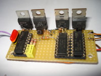
This winch may be used to control the sails of a sail boat model. The picture shows only the electronic board. The electrical motor and its reducer are not shown, they are at will ! (but must be within the output FET transistors characteristics).
I read Elektor from the first Elektor issue, but I never found such a scheme (or I have Alzheimer illness !).
I send this scheme to Elektor, but I have no sailboat to test is really : who want to test it on it's sail boat ?
I designed this scheme because specific components are difficult to purchase, and you surely have these 3 DIL gates in your lab ! This allows you to modify it at your will.
The input signal is a pulse from 1 ms to 2 ms (each 20 ms), at 5Vcc, coming from a receiver/decoder of a RF remote control.
On the mechanical drawing, the spring is for the rope tension: this will avoid the rope "jaming" in your model. The 3 to 5 dead turns of the rope are for adherence of the rope on the drum, for precise drive of the sails.
Today, the 49 cm stroke is run in 6 seconds, but it depends on the motor, the reducer and the potentiometer. (I'll nextly post movie showing the operation !)
This servo-winch may also be used as a standard servo by using 270° potentiometer, rather than the multi-turn potentiometer. See the linearity curve !
Enjoy your boat race !
Version française (2015-12-25)
Ce servo-treuil électronique ne comporte aucun composant spécifique, uniquement des portes 40xx. Besoin de quoi d'autre ?
Ce treuil peut être utilisé pour commander les voiles d'un modèle réduit de bateau à voiles. Les photos ne montrent que le circuit électronique. Le moteur électrique et le réducteur sont à la discrétion de chacun (mais ils doivent correspondre aux caractéristiques des transistors FET ! )
Je suis lecteur d'Elektor depuis le 1er numéro, mais je n'ai jamais vu un tel circuit (ou bien je suis atteint d'Alzheimer. . . )
J'avais envoyé ce schéma à Elektor, mais je n'ai pas de maquette de bateau à voile : qui veut essayer ce servo sur son bateau ?
J'ai développé ce schéma car les composants spécifiques sont difficiles à trouver dans le commerce. Vous avez tous sûrement les 3 boitiers DIL dans vos fonds de tiroir. Et vous pouvez adapter ce schéma selon vos besoin (c'était l'esprit initial d'Elektor : EXPERIMENTER).
Le signal d'entrée doit être une impulsion de 1 à 2 ms toutes les 20 ms, en 5 Volts, venant d'un récepteur et décodeur d'une télécomande.
Sur le schéma mécanique, le ressort sert à tendre la corde et éviter ainsi les problèmes. Faire 3 à 5 "tours morts" sur le galet d'entrainement, pour une meilleure adhérence et donc une commande plus précise.
Avec ce montage, le treuil tire 49 cm de corde en 6 secondes, mais cela dépend essentiellement du moteur, du réducteur et du potentiomètre.
Ce servo-treuil peut être utilisé en servo-moteur "ordinaire", en utilisant un potentiomètre de 270°.
Voyez la courbe de linéarité ! Excellent, non ?
Bonne régate !
Want to build a project?
Bring your design to life with the Elektor PCB Service, powered by Eurocircuits. Upload the project files and order professionally manufactured PCBs or assembled boards through a proven European production platform.
Supporting KiCad, Eagle, Gerber, and ODB++ formats, the service is suitable for everything from prototypes and validation builds to series production and volume manufacturing.
Made in Europe. Fast. Reliable. Professional.
Discussie (5 opmerking(en))