WebServer for Wide Area and Local Area Control & Monitoring

Not another Web Server! Why?- Fast: 32Bit 250Mhz Processor, 64MB RAM, 8MB Flash- Easy to make: Majority of system comes on mini PCMIA card, 1/2 the size of a credit card- Easy to program: Embedded RTOS integrated with: TCPIP stack, HTTP, DCHP, FTP, email and File System. With just 6 lines of code, just load your web pages onto the SD card and go!
Not another Web Server! Why?
- Fast: 32Bit 250Mhz Processor, 64MB RAM, 8MB Flash
- Easy to make: Majority of system comes on mini PCMIA card, 1/2 the size of a credit card
- Easy to program: Embedded RTOS integrated with: TCPIP stack, HTTP, DCHP, FTP, email and File System. With just 6 lines of code, just load your web pages onto the SD card and go!
- Easy to program and Debug:. Full integrated Eclipse based IDE and debugging. No hardware needed. Debug is via Ethernet connection
The project creates a compact, good looking, fast, flexible, powerful web server, with multiple communications options which is easy to configure. Based on the Netburner platform using the Coldfire 54415 32 bit processor which comes with free IDE and development tools, this embedded development environment allows for programming in C/C++ with all the hardware specific functionality taken care-of so there is no need for any Coldfire specific knowledge. Every library provided is fully integrated with the uC/OS RTOS and this makes development very fast and relatively easy and bug free. Here is the code required to establish a fully functioning Web Server to Serve web pages located on the SD Card:
InitializeStack(); // Initialise TCP Stack
GetDHCPAddress(); // Get IP address using DHCP
OSChangePrio(MAIN_PRIO); // Set the User Task Priority
f_enterFS(); // Initialise the File System
StartHTTP(); // Start the HTTP Server
while (1) OSTimeDly(20); // Do something or not
The debugging system is powerful with no required hardware. It uses Ethernet.
The Project:
The project is based on the Netburner NANO54415 miniPCMIA card (50 x 30mm) which contains the processor, the memory, 3V power, and Ethernet. Added to this are:
- mini-USB CDC Device
- USB Host supporting CDC / MS / Web Cam
- RS485/422 interface
- RS422 interface
- Serial TTL interface
- Ethernet connector
- ZigbeePRO module wither external antenna
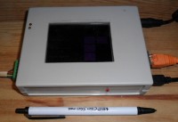
- LCD QVGA 340x272 4.3" touch display
- uSD Card slot
- alarm indicators
The system is easy to build and fits very nicely into a 130x100mm case. The PCMIA connector and standard SO SMD devices are relatively easy to solder; the only item that poses any construction challenge is the FTDI USB interface chip. This can always be substituted with another chip that uses standard SO pin spacing.
Communications software:
The Ethernet interface is already embedded into the system so there is no requirements in this area. To communicate to remote measuring devices in the field then use:
- UHF interface with single hop range of 20km, mulit-hop of 100km, up to 250 devices. This includes error correction.
- RS485/422 as per standard capability
- Zigbee as per standard capability. This is a Digi ZigbeePRO module with external antenna for extended range
The software used for communications can be ElektorBus, but because this system is designed to collect information from thousands of sensors, including images, then a tight packed proprietary protocol is used. The data is captured and stored in data files on the SD card, and this is made available to the Web Sever for displaying the images, and graphing the data over time.
Interface software.
The majority of the display software is written in HTML and operated by the Web Client. The LCD Menu and interface is limited to mainly simple configuration and diagnostic uses, and camera positioning, but of course its capability can be expanded. The Web Server has the ability to configure the majority of the system, display the images that have been captured by remote devices, and display graphs of the measured data over time. The software used to display the charts is 'highcharts' which is a downloadable java script library that the Web Client can take advantage of. The software also uses Google maps to show where all the remotes are located, if you are using the long distance capability of the UHF radios.
This system can be used to interface to any other monitoring and control system, however, it was originally designed to communicate with another project I have created called 'Pilot', which is a wide area fully isolated monitoring and control system capable of up to many thousands of simultaneous measurements.
Sensors.
One of the Devices this Web Server communicates with is a Isolated DC Remote that provides fully electrical isolated measurements of DC voltage, DC current, Temperature, digital inputs/Timers/counters and digital/PWM outputs. These measurements and controls are also isolated from the DC supply and communcations channels. The Isolated DC Remote is presented as an additional project on Elektor-labs
Discussie (3 opmerking(en))
Stacy Markel 6 jaar geleden
Lachlansp 6 jaar geleden
Lachlan 10 jaar geleden
I have tested the Vinculum I and Vinculum II USB Host chip in both UART and SPI mode, it has been a chore and not totally successful. Althought I managed to improve the throughput to a reasonable speed by using DMA (there was no information on how to improve speed and FTDI provided no guidance here), the SPI mode became extremely onerous and the UART mode did not meet my objectives. In time I could probably get this to work satisfactorily but decided not to proceed.
I have now done some testing with the MAX3421 USB Host chip with some good success. Still a lot more code to be done, but now there is an Arduino board with the chip, so there may be some reference code out there.
I have added the updated schematic.
I have decided to stick with teh FTDI based LCD as the performance is very good and FTDI have provided a work-around for updating just one part of the entire screen. Not an ideal solution, but the performance is still good, and I get the benefit of the other capabilities of the FTDI chip.
I soon as I am confident all is good with the USB host in Mass Storage mode, I will make the uSD card internal again and use file-to-file transfer to upload configurations and download data rather than removing the card and doing it manually.
Overall performance is very good. After further testing the USB Host, I will schedule the baord to be built.
Lachlan 11 jaar geleden
After testing the system I have encountered 2 issues. The hardware itself works entirely as planned except for the RS485 pull-up and pull-down resistors on the incorrect lines. However, the LCD performance is poor and updates are slow so I prose to change the LCD. In addition, system configuration has the potential of wiping all data from the attached SD Card so I propose adding USB Host ability to transfer configurations and upload data files for external manipulation.
LCD
The LCD is noticably slow to update. This is not a problem with system performance because the processor idle time is over 90% and updates are managed by a low priority task, but it does add latency to the SPI channel. This is not a problem for this design because the only other SPI device on this channel is the Zigbee which only requires access when a full data packet is received and latency is not a serious issue. So the problem is mainly the user experience.
In Version 2 schematic i have added a 4.3' Touch LCD, (up from 3.4') from Elektronica using the FTDI Eve chip. This significantly improves perfomance but shows two further issues:
a. The LCD uses display lists which is very efficient, except when a small change is required (such as when monitoring a sensor or displaying status updates), in which case the entire display list needs to be resent. (but still has much improved performance and lower SPI channel latency over the V1 LCD).
b. When displaying graphs each pixel has to be indentified with its location and there is a limit to the display list memory. Therefore a maximum of two graphs can be displayed, and text must be sent as pixels. (This is less of a problem as most graphs are expected to be done in the web client, but still there is an advantage in having a local display capability).
Questions
1. Has anyone used an FTDI based LCD, and if so, how did you overcome the problem of performing small updates to a complex display?
2. Also, how have you managed to display a large number of graphs (eg. 4) that would normally exceed the chips display list memory?
3. Is is prudent to use something like an Atmel xmega32E5 with 2 SPI channels, to act as an interim controller and create my own, more efficient LCD interface commands? (This does not seem very hardware efficient and adds an extra program to the system that has to be maintained)
4. Has anyone used a really good 4.3' LCD touch screen with SPI interface that overcomes these problems?
USB Host
At present slave configuration information is created elsewhere and imported directly to the SD card using FTP. Although local configuration of slaves can be acheived for devices like the DC Remote that I have also proposed on this website, there are more complex devices that contain hundreds of channels (i will post another project at a later stage) so it does not make sense to do configurations here. The FTP transfer process can potentially upset the data on the SD card by overriding an important configuration file.
To overcome this I propose a USB Host (see Schematic) that can read configurations files from a USB stick and place them in the correct location (and check them), and also to allow data files to be uploaded if further processing is required other than the standard Web page display. This provides the added advantage of allowing a webcam to be attached, similar to the camera capability of the remotes (but at this stage i dont see the need for a camera at the central site). Note that the USB Host chip needs to be programmed, also causing an additional program that needs to be maintained. (The USB host capability can be perfomed by the Netburner module but this would require purcahsing software or extensive software development).
Questions
a. Is it worthwhile adding the extra hardware for a USB Host for the extra gain of data integrity?
b. Has anyone had experience using the FTDI Vinculum-II chip for a USB host and can share any issues?
c. Does anyone have experience of a good USB host controller that they can share?
External SD Card access
A fourth change i have done for V2 is to allow the SD card to be accessed externally. I am not sure if this is a good idea because removing the card while the system is running will cause the system to fail until the SD card is replaced, as the configuration files and data files are located on the SD Card. Also, removing the card allows someone to damage the integrity of the configuration and data files.
Question
a. What are other peoples experience here? Is it best to leave the SD card internal and have it as internal memory, or provide external access. If the USB Host function is used I can change the SD card to internal. If I dont go with the USB Host then the external access allows for data files to be retrieved for further processing.
Thanks for any help
Regards
Lachlan
FTDI 11 jaar geleden
Lachlan 11 jaar geleden