
Comfortable and Inexpensive V-A Controller (CIVAC)
It's a simple box with diverse inputs and outputs to help control easily V and A of a working device.
The power supply unit of one of my cordless phones died, so I went to my usual phone equipment seller booth and I was presented with a box full of dozens of jumbled power supplies. I need to say that I live in Ouagadougou, Burkina Faso and there you can’t find a specialty store where you just find electronic equipment you need.
The original block supplied 7.5 V at 500 mA. Not having found a block with identical characteristics I bought one of 7,8V at 500 mA that could probably do the trick. But once connected, the phone still doesn’t charge.
This is where the CIVAC comes in. It was the question of knowing why this power supply did not charge the phone.
So I plugged the CIVAC between the power supply and I found that once connected the block voltage collapsed. I had just to go back to buy another one ...
The only other block I found with features approaching the original power supplied was 5.7 V at 800 mA, and when plugged it just charged the phone without problem...
What are the characteristics that make it comfortable controller, it has multiple inputs and outputs that adapt to different power connectors.
If necessary, it’s possible to add the connectors we need.
The USB connectors are particularly useful for checking the current supplied to devices connected to this port and why not, you own homemade USB devices.
CIVAC avoids making "wild" connections that may caused short circuits. CIVAC adapter can also be used when the connector from the power supply under test is different from those we have at hand.
However, it is important to check that the polarity of the supply and the device to be supplied are the same, since a polarity reversal can be fatal to the connected device.
For convenience, it is possible to add a switch to short cut the connection between the 2 banana sockets for the ammeter if we don’t need to check the amperage.
From a practical standpoint, making this utility is quite easy.
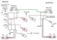
For the inputs, simply place the different front panel power supply jacks, a 9V battery coupler, and an USB connector on one side of the selected case.
For the outputs, will be placed on the opposite side of the case, the power supply connectors, another 9V battery coupler and another USB connector. As output, it is possible to place a power jack with interchangeable “heads”, it will reduce the wiring and welding and the risk of tangling wires.
Between the two sides, we will place the 2 red and black banana sockets to connect the voltmeter, and the other 2 red and black banana sockets to connect the ammeter.
For the inputs, all masses are connected together and to the black socket of the voltmeter, all the “hot” wires are connected together and to the red voltmeter and the red ammeter sockets.
For the outputs, all grouds are connected together and to the black voltmeter socket, which is the common ground to inputs and outputs, all the “hot” wires are connected together and to the black ammeter socket.
Be careful with the polarity of 9V batteries couplers, in fact, the connections are crossed. On input, the module receives a 9V battery and therefore the "plus" is the hex connector. As output, the 9V battery coupler behaves like a battery, the "plus" is then the round connector.
Do not forget to connect the data pins of the 2 USB connectors, as shown on the drawing, so that the connected device is recognized and one can measure the current consumed in working situation.
The original block supplied 7.5 V at 500 mA. Not having found a block with identical characteristics I bought one of 7,8V at 500 mA that could probably do the trick. But once connected, the phone still doesn’t charge.
This is where the CIVAC comes in. It was the question of knowing why this power supply did not charge the phone.
So I plugged the CIVAC between the power supply and I found that once connected the block voltage collapsed. I had just to go back to buy another one ...
The only other block I found with features approaching the original power supplied was 5.7 V at 800 mA, and when plugged it just charged the phone without problem...
What are the characteristics that make it comfortable controller, it has multiple inputs and outputs that adapt to different power connectors.
If necessary, it’s possible to add the connectors we need.
The USB connectors are particularly useful for checking the current supplied to devices connected to this port and why not, you own homemade USB devices.
CIVAC avoids making "wild" connections that may caused short circuits. CIVAC adapter can also be used when the connector from the power supply under test is different from those we have at hand.
However, it is important to check that the polarity of the supply and the device to be supplied are the same, since a polarity reversal can be fatal to the connected device.
For convenience, it is possible to add a switch to short cut the connection between the 2 banana sockets for the ammeter if we don’t need to check the amperage.
From a practical standpoint, making this utility is quite easy.
For the inputs, simply place the different front panel power supply jacks, a 9V battery coupler, and an USB connector on one side of the selected case.
For the outputs, will be placed on the opposite side of the case, the power supply connectors, another 9V battery coupler and another USB connector. As output, it is possible to place a power jack with interchangeable “heads”, it will reduce the wiring and welding and the risk of tangling wires.
Between the two sides, we will place the 2 red and black banana sockets to connect the voltmeter, and the other 2 red and black banana sockets to connect the ammeter.
For the inputs, all masses are connected together and to the black socket of the voltmeter, all the “hot” wires are connected together and to the red voltmeter and the red ammeter sockets.
For the outputs, all grouds are connected together and to the black voltmeter socket, which is the common ground to inputs and outputs, all the “hot” wires are connected together and to the black ammeter socket.
Be careful with the polarity of 9V batteries couplers, in fact, the connections are crossed. On input, the module receives a 9V battery and therefore the "plus" is the hex connector. As output, the 9V battery coupler behaves like a battery, the "plus" is then the round connector.
Do not forget to connect the data pins of the 2 USB connectors, as shown on the drawing, so that the connected device is recognized and one can measure the current consumed in working situation.
Want to build a project?
Bring your design to life with the Elektor PCB Service, powered by Eurocircuits. Upload the project files and order professionally manufactured PCBs or assembled boards through a proven European production platform.
Supporting KiCad, Eagle, Gerber, and ODB++ formats, the service is suitable for everything from prototypes and validation builds to series production and volume manufacturing.
Made in Europe. Fast. Reliable. Professional.
Discussie (0 opmerking(en))