
140409 Power Meter
Project is updated: look for additional information in contribution Updated version 1.1 of Power Meter 140409-1 One of our projects is the Practical 4 Channel ADC (called ADS1115-BOB in our shop, 140169-91). But what kind of applications are suitable for A/D converters with a slow sample rate.
Project is updated: look for additional information in contribution Updated version 1.1 of Power Meter 140409-1
One of our projects is the Practical 4 Channel ADC (called ADS1115-BOB in our shop, 140169-91). But what kind of applications are suitable for A/D converters with a slow sample rate. In this case the maximum sample rate is 860 Hz. One of the first ideas was a power meter. For DC you can measure voltage and current with a multimeter and multiply the two results. You can buy cheap power meters for 15 euro’s to measure power consumption of various appliances like computers and digital receivers etc. Of course our circuit should be capable of much more. There should be an analog output for an oscilloscope or multimeter present at least. The circuit must provide a way to measure potentially lethal mains and DC voltages and currents in a safe way.
One way of making an isolated amplifier is the use of optocouplers and ordinary opamps. This means a fairly large amount of parts. Another option is the use of isolation amplifiers, especially designed for this purpose. One of those is the AMC1100 from Texas Instruments. It has a minimum bandwidth of 60 kHz and a galvanic isolation of 4250 Vpeak (working voltage 1200 Vpeak). Using this amplifier will give the circuit a class II grade isolation and makes the circuit very safe. It comes in a gullwing-8 SMD package (it looks like a DIP-8 with bended pins). Of course the isolation amplifier needs two supply voltages, one for the input side and another one for the output side. The use of standard power supply modules that produce an unregulated galvanic isolated voltage is one way, but usually these are not specified for class II and more components like an additional voltage regulator are needed. A better solution is the use of an integrated circuit specifically designed for this. The ADuM6000 from Analog Devices is an isolated DC-to-DC converter with regulated 5V or 3.3 V output. VIORM is 846 Vpeak.
The simplest way of measuring current is to put a resistor in series and measure the voltage across. Almost all multimeters do the same. To influence the circuit to test as little as possible the shunt has to have a low value. Depending on the maximum range of the current input, a low power loss is another reason. If a very low resistance is used, the voltage across the shunt can always be amplified. The isolation amplifier (IC2) has a differential input with a switched capacitor circuit. Output noise is specified as 3.1 mVRMS, with no further details. If this is a specification with the full bandwidth taken into account, noise levels will be less if the bandwidth is limited before the ADC. A filter with four channels designed with a 1 kHz bandwidth is to be found elsewhere on elektor-labs (140169-2 Filter for Practical 4-channel ADC). Input signal should be limited to 250 mV (differential). The AMC1100 amplifies 8 times, so the maximum output signal (linear) is 2 V. Without the filter the S/N would be 645. With the filter it’s √60 times higher, so 5000. This means we can measure smaller signals. To increase sensitivity an amplifier with selectable gain is added in front of the isolation amplifier (IC1). IC1 is a AD8639 and is an auto zero rail-to-rail output opamp. Input offset is 3 µV typical (9 µV max.). Maximum offset drift is only 0.06 µV. So an excellent choice for DC measurements. Gain Bandwidth Product is 1.35 MHz. Bandwidth of this amplifier with maximum gain selected is more than 10 kHz, enough for our purposes. IC1 is configured as an instrumentation amplifier where the differential gain is 1 + 2 x (R6+R7)/RG, where RG is R4 or R5. Without jumper JP1 this gain (the voltage between the outputs of IC1A and IC1B in relation to the voltage across R1) is 1. If R4 is selected the gain is 10 and with R5 it’s 100. Despite the E24 values the gain settings are exact (of coarse within resistor tolerances) If the output voltage of IC2 is maximal 2 V, the 3 full scale ranges of the current input are 17.7 A (1 x), 1.77 A (10 x) and 0.177 A (100 x), for a sine wave. The maximum RMS value of signals with large crest factors will be less. Depending on the noise level the minimal current that can be measured with the ADC is less than 0.1 W. This is the case if the ADC still has a descent signal at -50 dB full scale.
Like mentioned before, the circuit can also be used to measure high voltages safely with an oscilloscope or multimeter. The differential outputs of the AMC1100s are not adequate as an output for that purpose, we rather have a single ended output. Difference amplifier IC4 (another AD8639) converts the differential signals into single ended ones (with same amplitude). The common mode offset (2.55V@VDD=5V typ.) on the outputs of the AMC1100 are reduced to almost 0 V, but not fully. Depending on difference of the DC voltage between the individual outputs of the AMC1100 there will be a small offset in the order of a few millivolt at the outputs of IC4. The input offset is 0.2 mV typical and 1.5 mV maximal. So the output offset should always be less than 12 mV. Input offset drift of the AMC1100 is 10 µV/ °C maximal within the specified temperature range of -40 to +105 °C. So this offset will be stable with temperature. The common mode input range of the AD8639 is -0.1 V to 3 V max. with a 5 V power supply. Voltage divider R21/R22 (R25/R26) lowers the 2.55 V of the AMC1100 to 1.275 V. We measured a maximum output signal of the AMC1100 of approximately 2.5 V. The maximum voltage on the inputs of IC4 can’t be more than 1.9 V (1.275 VDC plus half of the peak AC voltage). This is well within the common mode range of the AD8639.
Most of the ICs only need a single 5 V power supply. IC4 however also needs a negative power supply to produce an AC signal without a DC offset but we also want to measure DC voltages. The outputs on K6 have to be able to produce negative voltages. We made a virtual ground by placing a zener diode in the ground pin of IC6. IC6 is a low drop regulator. We used a zener diode (D7) of 1.8 V. It’s specified at 50 µA. Strangely enough the voltage over D7, with close to 80 mA flowing through it, is about 4.1 V. So the total input voltage for the regulator IC6, zener diode D7 and input polarity protection diode D8 is minimal 10 V, preferably 12 V.
The power supply for the isolated side is produced by an ADuM6000. It has an integrated regulator delivering 3.3 V or 5 V at a 5 V input but only 3.3 V with 3.3 V input. We set it for 5 V by connecting Vsel with Viso. For more information please refer to the datasheet and application notes
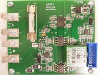
To prevent the signal from the shunt getting outside the common mode range of IC1, shunt R1 is connected to +2 V (we measured 1.9 V in our prototype). Led D5 is used as a reference diode to produce a virtual ground, but we called it +2 V. D5 is also the power supply indicator for the isolated side. The +2V is also connected to voltage divider R1..R16 for the voltage measurement. The shunt and the voltage divider are connected to the same input connector. We used faston types which are screwed onto the PCB to ensure good mechanical and electrical contact, especially useful if thick wires are used. Advantage is also that the contact can be pulled of and no screwdriver is necessary. Although the common mode input range of the AMC1100 extends from the positive power supply line to -0.16V, it’s not advisable to use a component so close to its limit. The maximum voltage across R16 is depends on the maximum voltage rating of the fuse used. The fuse we used is specified for 500 VAC and 300 VDC. In the case of the maximum 500 VAC the voltage across R16 is about 85 mV. In software a calibration routine is needed for both voltage and current.
To control module 140169-91 (ADS1115-BOB) we connected it to our Arduino Extension Shield (140009-91) mounted on an Arduino Uno. The shield has an EEC connector (K2) and can be connected to K5 here. We only need the I2C signals and a GPIO. The Arduino and the power meter need separate AC adapters. The software will be discussed in separate contribution.
Bill of materials
Resistor
R1 = 0Ω01, 2 W, 1 % (Ohmite FC4L64R010FER)
R2,R3 = 22 Ω, 0W25, 5 %, SMD 0805
R4,R31,R33 = 2k20, 0W125, 1 %, SMD 0805
R5 = 200 Ω, 0W125, 1 %, SMD 0805
R6,R8 = 5k6, 0W125, 1 %, SMD 0805
R7,R9 = 4k3, 0W125, 1 %, SMD 0805
R10,R11,R17,R18 = 12 Ω, 0W125, 1 %, SMD 0805
R12,R13,R19,R20,R29,R30 = 47 Ω, 125 mW, 1 %, SMD 0805
R14,R15 = 220 kΩ, 1W5, 1 %, 500 V, SMD 2512
R16 = 75 Ω, 0W125, 1 %, SMD 0805
R21-R28 = 100 kΩ, 0W125, SMD 0805
R32 = 39 kΩ, 0W125, 5 %, SMD 0805
Capacitor
C1,C2 = 1 nF, 50 V, 5 %, SMD 0805, C0G/NP0
C3,C7,C11,C14,C23,C24 = 100 nF, 50 V, 10 %, SMD 0805, X7R
C4,C15,C17,C19,C21 = 10 µF, 10 V, 10 %, SMD 0805
C5 = 100 µF, 6V3, 20 %, SMD Case A (1206), tantalum
C6,C10 = 330 pF, 50 V, 5 %, SMD 0805, C0G/NP0
C8,C9,C12,C13 = 100 nF, 50 V, 10 %, SMD 1206, X7R
C16,C18,C20,C22 = 100 nF, 25 V, 10 %, SMD 0603, X7R
C25,C26 = 4µ7, 6V3, 10 %, SMD Case R (0805), tantalum
C27 = 10 µF, 25 V, +80/-20%, SMD 1206, Y5V
Inductor
L1 = 600 Ω @ 100 MHz, 0R15, 1.3 A, SMD 0603
Semiconductor
D1,D2,D4 = HSMS-2822-TR1G, SMD SOT-23
D3 = SP0502BAHTG, SMD SOT-23
D5,D6 = Led green, SMD 0805
D7 = MMSZ4678T1G, SMD SOD-123 (Zener 1V8/0W5)
D8 = PMEG2010AEH, 20 V/1 A, SMD SOD-123F
IC1,IC4 = AD8639ARZ, SMD SOIC-8
IC2,IC3 = AMC1100DUB, SMD Gullwing-8 (SOP-8)
IC5 = ADuM6000ARWZ, SMD RW-16 (SOIC_W-16)
IC6 = NCP5501DT50G, SMD DPAK3
Other
K1-K4 = 6.35 mm Terminal, Faston, Screw, hole 3.3 mm
K5 = 14way header (2x7), straight
K6,JP1 = 3way pinheader SIL, pitch 2.54 mm
K7 = 2way pinheader SIL, pitch 2.54 mm
F1 = Fuse Clip, PCB, 32 A, 600 V (6.3 x 32 mm), Schurter 8040.0001
F1 = 10 A fuse, 500 VAC/300 VDC, antisurge, 6.3 x 32 mm
Misc.
PCB 140409-1 v1.0
Module 140169-91
Want to build a project?
Bring your design to life with the Elektor PCB Service, powered by Eurocircuits. Upload the project files and order professionally manufactured PCBs or assembled boards through a proven European production platform.
Supporting KiCad, Eagle, Gerber, and ODB++ formats, the service is suitable for everything from prototypes and validation builds to series production and volume manufacturing.
Made in Europe. Fast. Reliable. Professional.
Discussie (1 opmerking(en))