
A Universal RLC-Box
Select a value out of 7...8 decades from resistance, capacitance and inductance and connect them in series, parallel or isolated from each other,
The Box is now available for sale here:
https://www.ak-modul-bus.de/stat/laborzubehoer.html
When developing electronic circuits (or repairing devices) you often have to determine experimentally the value of a resistor, capacitor or inductor. Sometimes you even have to insert a little highpass or lowpass-filter and determine the best cutoff-frequency.
So instead of testing this with dozens of components or combinations of combinations on a breadboard take a look at this versatiel RLC-Box.
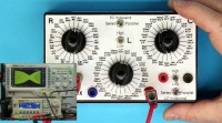
With the rotary switches you can quickly select a resistor (1 Ohm...100 Megohms), a capacitor (10pF...1.000µF) or an inductor (10nH...150mH).
Best is that with 2 additional triple-throw switches you can connect the 3 components in series or parallel combinations.
That way you can easily create a variable lowpass-, highpass-, bandpass-, bandstop-filter or a RLC tank-circuit (series or parallel).
I created the prototype for my own demands many years ago. When I was using it on one of my YouTube-Videos there always were people asking if and where this box is available.
https://www.youtube.com/Kainkalabs
So I finally decided to polish it up a bit, create PCBs for the rotary switches and the faceplate and make this available as a Kickstarter project:
https://www.kickstarter.com/projects/rogerleifert/a-versatile-rlc-box-for-the-electronics-lab
After the campaign ends I will publish the PCB-files under the Open Source Hardware license. But don´t expect that you can save a lot of money by building one of your own.
The cost for the major parts + PCBs + case add up to more than 100 Euros in volume.
In the mean-time I will publish here and on the kickstarter page some progress reports and background info.
If you have any suggestions or ideas for improvement, please comment
Roger
https://www.ak-modul-bus.de/stat/laborzubehoer.html
When developing electronic circuits (or repairing devices) you often have to determine experimentally the value of a resistor, capacitor or inductor. Sometimes you even have to insert a little highpass or lowpass-filter and determine the best cutoff-frequency.
So instead of testing this with dozens of components or combinations of combinations on a breadboard take a look at this versatiel RLC-Box.
With the rotary switches you can quickly select a resistor (1 Ohm...100 Megohms), a capacitor (10pF...1.000µF) or an inductor (10nH...150mH).
Best is that with 2 additional triple-throw switches you can connect the 3 components in series or parallel combinations.
That way you can easily create a variable lowpass-, highpass-, bandpass-, bandstop-filter or a RLC tank-circuit (series or parallel).
I created the prototype for my own demands many years ago. When I was using it on one of my YouTube-Videos there always were people asking if and where this box is available.
https://www.youtube.com/Kainkalabs
So I finally decided to polish it up a bit, create PCBs for the rotary switches and the faceplate and make this available as a Kickstarter project:
https://www.kickstarter.com/projects/rogerleifert/a-versatile-rlc-box-for-the-electronics-lab
After the campaign ends I will publish the PCB-files under the Open Source Hardware license. But don´t expect that you can save a lot of money by building one of your own.
The cost for the major parts + PCBs + case add up to more than 100 Euros in volume.
In the mean-time I will publish here and on the kickstarter page some progress reports and background info.
If you have any suggestions or ideas for improvement, please comment
Roger
Updates van de auteur