
Acoustic IR-remote control tester [200025]
IR-receiver drives a small loudspeaker. Hear the IR remote control. Compare universal with the original. Each code sounds different. Fun and useful.
Did you ever ask yourself what an IR-remote control sounds like? Here’s a simple circuit that uses the output signal of an IR-receiver (IC1) to drive a loudspeaker. A divider (IC2) is used to lower the frequency to better fit the range of the small loudspeaker used. This way you can test almost any remote control and compare a universal one with the original. It also reveals that different manufacturers use the same code; the remote controls sound the same. For instance, the remote control of a media player from Popcorn Hour sounds the same as the remote control of digital receiver from Humax. A RC5 type remote control for instance sounds quite different from a NEC code version. The IR-receiver module from Vishay used is available for a variety of frequencies, 30, 33, 36, 38, 40 and 56 kHz. RC5 uses a modulation of 36 kHz. In our prototype a TSOP4836 was used also worked with other modulation frequencies if they are not too different.

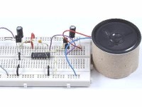
In the schematic output 9 of the 4040 gives “best” sound, but that depends on personal preference and the miniature loudspeaker used. This output divides the input signal (f) at pin 10 by a factor of two. Other outputs can be used and even the input signal at pin 10. The reset of the 4040 (pin 11) isn’t used and connected to ground. The output signal is buffered by a complementary emitter follower, the transistors used are not that critical and many other types will do. Just check the connections in their datasheets if unsure. Any cheap small loudspeaker can be used since the output power is in the mW range. R2 is used as a short circuit protection. To prevent an acoustic short circuit (pressure behind the loudspeaker cancels out the pressure in front of it, but mainly at lower frequencies) always place the loudspeaker in a closed box for the lower frequencies to be audible. Here a short cut piece of a cardboard paper towel roll is used.
R1 and C1 decouple the power supply of the IR-receiver to avoid interference on the +3 V power supply caused by the output stage. According to the datasheet a TSOP4836 works from +2.5 to +5.5 V. So, two AA batteries can be used as a power supply, or even three. You can also connect the circuit to an available +5V power supply. A 74HCT4040 will also work on 3 V, although specified for 4,5 to 5,5 V to be compatible with the old TTL levels. A 74HC4040 however is specified to work from +2 to +6 V and is the better choice for this circuit. The IR-receiver output levels are practically the same as the power supply, so no TTL levels here (the TSOP48xx has an internal pull-up), hence the lower acceptable power supply voltage for the HCT version of the 4040 for this circuit.
Depending on the IR-code the maximum power supply current measured is about 13 mA but maybe a few mA more. With no IR-signal the power supply current is about 0.66 mA. Any other similar IR-receiver module can also be used, but quiescent current may be different.
Discussie (0 opmerking(en))