
Advent calendar with Raspberry Pi Ruler Gadget
Distance measurement until Christmas Eve with 24 LEDs using Elektor Raspberry Pi ruler gadget
Distance measurement until Christmas Eve
Elektor's Raspberry Pi ruler gadget has 22 LEDs. These can be used to show the result of a distance measurement with a VL53L0X sensor. In keeping with the pre-Christmas period, the board can also be used in other ways to measure the distance to Christmas Eve without any additional sensor. A small Raspberry Pi Zero is used to control the LEDs depending on the current date. For a classic advent calendar, however, 24 LEDs are necessary, but that should be no problem because we just add 2 more LEDs outside the ruler PCB, so we have 24 LEDs on totally 24 cm length.
Hardware
The schematic is very simple and is attached below.
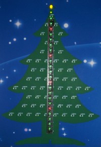
To make the Advent calendar look Christmassy, we stick the Ruler Gadget with a cardboard with a Christmas tree motif. In proper style it should of course be an Elektor Christmas tree, so we have used the PCB Christmas tree motif from Elektor 12/2014, which we found on the website https://www.mikrocontroller.net/attachment/237565/Tannenbaum2.JPG. The left tree on that image is printed on the size of a DIN A4 page, cut out and pasted on a cardboard with a starry sky as a background. In the middle of the tree a rectangular of 1.2 cm x 22 cm is cut out, so that later on the 22 LEDs of the Ruler Gagdet are visible there. The top edge of the recess should be 2 cm from the center of the star at the top of the tree so that the two additional LEDs have the same distance as the other LEDs on the Ruler. The cardboard is then attached with double-sided adhesive tape and sticky tape fitting on the Ruler board, as seen in the photos.
On the Ruler gadget a red LED is used for every fifth LED (that is LED5, LED10, LED15 and LED20), the remaining LEDs are green. The red LEDs in the fivefold grid significantly simplify the quick reading of the value from a distance. For the two external additional LEDs we use a green LED with 3 mm diameter and a yellow LED with 5 mm diameter. These are inserted at the correct distance from the front of the cardboard and soldered on the back on a small breadboard with solder points with 2.54 mm pitch, so that the small additional board is also mechanically fastened by the LEDs. The holes can be pierced with a sewing needle. On the solder side of the breadboard the two series resistors also find place. With 3 copper wires the connection to the Ruler board takes place. The connector pins 7 and 13 of the Raspberry Pi are accessible on the pads for the connection of the VL53L0X sensor of the Ruler board, so that the thread wires can be easily soldered there. P4 corresponds to connector pin 7 and P27 corresponds to connector pin 13.
Software
Now the appropriate software must be installed on the Raspberry Pi Zero. The first steps are the same as in points 1 through 4 of the manual as described on https://www.elektormagazine.com/labs/rpi-ruler under “Installation of the software on the Rpi". Then the new file "rpi_ruler_advent.c" is downloaded and placed in the directory
VL53L0X_rasp/examples
of the Raspberry Pi. An easy way to copy data from Windows to the Raspberry Pi is to connect to Wi-Fi (which is available on the Raspberry Pi Zero W, or for the older Raspberrys a USB WiFi stick can be used) and to use the tool WinSCP. Likewise, with the tool PuTTY an SSH connection can be set up to connect to the Raspberry via the console input window.
Then the program is compiled on the Raspberry Pi with the following commands starting from the home directory /home/pi of the Raspberry:
Then we switch off all LEDs again by specifying the parameter -2:
The parameter 0 activates the demo mode (a video can be seen on https://youtu.be/D4YQAPSBESI), so that the LED chain moves up and down at an interval of 4 LEDs:
With a numerical value of 1 to 24 as a parameter, the LED chain is built up step by step up to the numerical value and switched off after approx. one second, before the whole cycle is repeated cyclically. Example for all 24 LEDs (a video can be seen on https://youtu.be/D_1DBXY7W30):
When the program is called without parameters, the LEDs are automatically displayed dependent on the current date. From 1st to 24th December, the LED chain will be switched on cyclically until the respective day, on the remaining days the demo mode will run.
Now we set up the Raspberry Pi so that the program is started automatically at startup and runs in the background. On the console of the Raspberry we enter the following:
Then the Raspberry Pi needs to be rebooted with the following call:
If you want to terminate the program running in the background, the appropriate process must be killed. To do this, enter the following:
We wish you a nice Advent season!
Elektor's Raspberry Pi ruler gadget has 22 LEDs. These can be used to show the result of a distance measurement with a VL53L0X sensor. In keeping with the pre-Christmas period, the board can also be used in other ways to measure the distance to Christmas Eve without any additional sensor. A small Raspberry Pi Zero is used to control the LEDs depending on the current date. For a classic advent calendar, however, 24 LEDs are necessary, but that should be no problem because we just add 2 more LEDs outside the ruler PCB, so we have 24 LEDs on totally 24 cm length.
Hardware
The schematic is very simple and is attached below.
To make the Advent calendar look Christmassy, we stick the Ruler Gadget with a cardboard with a Christmas tree motif. In proper style it should of course be an Elektor Christmas tree, so we have used the PCB Christmas tree motif from Elektor 12/2014, which we found on the website https://www.mikrocontroller.net/attachment/237565/Tannenbaum2.JPG. The left tree on that image is printed on the size of a DIN A4 page, cut out and pasted on a cardboard with a starry sky as a background. In the middle of the tree a rectangular of 1.2 cm x 22 cm is cut out, so that later on the 22 LEDs of the Ruler Gagdet are visible there. The top edge of the recess should be 2 cm from the center of the star at the top of the tree so that the two additional LEDs have the same distance as the other LEDs on the Ruler. The cardboard is then attached with double-sided adhesive tape and sticky tape fitting on the Ruler board, as seen in the photos.
On the Ruler gadget a red LED is used for every fifth LED (that is LED5, LED10, LED15 and LED20), the remaining LEDs are green. The red LEDs in the fivefold grid significantly simplify the quick reading of the value from a distance. For the two external additional LEDs we use a green LED with 3 mm diameter and a yellow LED with 5 mm diameter. These are inserted at the correct distance from the front of the cardboard and soldered on the back on a small breadboard with solder points with 2.54 mm pitch, so that the small additional board is also mechanically fastened by the LEDs. The holes can be pierced with a sewing needle. On the solder side of the breadboard the two series resistors also find place. With 3 copper wires the connection to the Ruler board takes place. The connector pins 7 and 13 of the Raspberry Pi are accessible on the pads for the connection of the VL53L0X sensor of the Ruler board, so that the thread wires can be easily soldered there. P4 corresponds to connector pin 7 and P27 corresponds to connector pin 13.
Software
Now the appropriate software must be installed on the Raspberry Pi Zero. The first steps are the same as in points 1 through 4 of the manual as described on https://www.elektormagazine.com/labs/rpi-ruler under “Installation of the software on the Rpi". Then the new file "rpi_ruler_advent.c" is downloaded and placed in the directory
VL53L0X_rasp/examples
of the Raspberry Pi. An easy way to copy data from Windows to the Raspberry Pi is to connect to Wi-Fi (which is available on the Raspberry Pi Zero W, or for the older Raspberrys a USB WiFi stick can be used) and to use the tool WinSCP. Likewise, with the tool PuTTY an SSH connection can be set up to connect to the Raspberry via the console input window.
Then the program is compiled on the Raspberry Pi with the following commands starting from the home directory /home/pi of the Raspberry:
cd VL53L0X_rasp
make API_DIR=~/VL53L0X_1.0.2/
make examples API_DIR=~/VL53L0X_1.0.2/
Then the program can be started by the following call:
./bin/rpi_ruler_advent -1
The parameter -1 activates the test mode to turn on all the LEDs one after each other.Then we switch off all LEDs again by specifying the parameter -2:
./bin/rpi_ruler_advent –2
The parameter 0 activates the demo mode (a video can be seen on https://youtu.be/D4YQAPSBESI), so that the LED chain moves up and down at an interval of 4 LEDs:
./bin/rpi_ruler_advent 0
Pressing the key combination Ctrl-C terminates the program.With a numerical value of 1 to 24 as a parameter, the LED chain is built up step by step up to the numerical value and switched off after approx. one second, before the whole cycle is repeated cyclically. Example for all 24 LEDs (a video can be seen on https://youtu.be/D_1DBXY7W30):
./bin/rpi_ruler_advent 24
Pressing the key combination Ctrl-C terminates the program.When the program is called without parameters, the LEDs are automatically displayed dependent on the current date. From 1st to 24th December, the LED chain will be switched on cyclically until the respective day, on the remaining days the demo mode will run.
Now we set up the Raspberry Pi so that the program is started automatically at startup and runs in the background. On the console of the Raspberry we enter the following:
sudo nano /etc/rc.local
This will open a text editor. Before the line "exit 0" we insert a new line:
/home/pi/VL53L0X_rasp/bin/rpi_ruler_advent &
The & at the end makes sure that the program rpi_ruler_advent, which was started at boot time, runs in the background.Then the Raspberry Pi needs to be rebooted with the following call:
sudo reboot
After the Raspberry Pi has rebooted, the program should be started automatically and show the corresponding days before Christmas Eve according to the current date or the demo mode on the LED display.If you want to terminate the program running in the background, the appropriate process must be killed. To do this, enter the following:
ps –ax | grep rpi
then search for the process “rpi_ruler_advent” in the list and enter the PID displayed on the left in the next command:
sudo kill PID
We wish you a nice Advent season!
Want to build a project?
Bring your design to life with the Elektor PCB Service, powered by Eurocircuits. Upload the project files and order professionally manufactured PCBs or assembled boards through a proven European production platform.
Supporting KiCad, Eagle, Gerber, and ODB++ formats, the service is suitable for everything from prototypes and validation builds to series production and volume manufacturing.
Made in Europe. Fast. Reliable. Professional.
Discussie (2 opmerking(en))