
AVR Playground [129009-2, 160316]
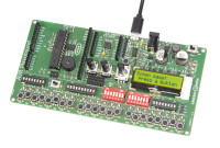
The AVR Playground is a hybrid of an Arduino Uno and a traditional microcontroller development board.
The board presented here is a hybrid of an Arduino Uno and a traditional microcontroller development board, intended for ‘doing Arduino’ without bad connections and loose wires (although it doesn’t disallow it).
Before the rise of Arduino, microcontroller development boards had on-board peripherals like pushbuttons and LEDs, a display, one or more potentiometers for analog signals, extension connectors, etc. and, of course, a decent power supply. The goal of these boards was to provide an easy way to start learning the microcontroller without having to solder or add other components. The AVR Playground – a playful reference to the Arduino forum known as the Arduino Playground – was designed with this in mind, and extended with things from Arduino that we have learned to appreciate.
The board can roughly be divided into four horizontal zones with, from top to bottom, the following functions:
The schematics, the PCB and the component list of the AVR Playground are available in the download section.
There is also a switch to select the MCU’s operating voltage, 3.3 or 5 volts. Two LEDs, blue (3.3 V, cold) and red (5 V, warm), indicate the actual board voltage. Refer to Tables 1 to 5 for details.
LCD
The display, a small LC one with backlight, has an I²C interface instead of the frequently seen 4-bit semi-parallel or 8-bit parallel interface. The evident advantage is that it only requires two wires for connecting it to the MCU. The inconvenience is the need for a special driver, but we took due care of that in the Boards Package (see below).
Rotary controls
Two potentiometers provide analog signals to the microcontroller. By positioning a jumper, they can be connected to any of the six analog inputs of the MCU without the risk of both being connected to the same input at the same time.
The rotary encoder is in reality the same thing as (up to) three pushbuttons hence it’s effectively connected in parallel to the pushbuttons on PD3, PD4 and PD5.
Arduino LED
The LED connected to PB5 (Pin 13) on the Arduino Uno is available on the AVR Playground too; it is located below the rotary encoder. This LED is used in many sketches, reason why it is present on this board.
In normal operation port PC6 functions as the reset input of the MCU. It is possible to disconnect it from its reset function by programing the MCU’s RSTDSBL fuse. However, that’s not recommended as it will disable MCU programming over the serial port and through the ISP connector. The only way to reprogram the MCU is to remove it from the board and land it in a so-called parallel programmer. Because disabling the reset input is incompatible with the objectives of the AVR Playground, PC6 is not treated like the other port pins and there is no LED connected to it (there is, however, a pushbutton for it: Reset).
Adding a new board to the IDE is not difficult and there is even a special tool for this: the Boards Manager, accessible at the top of the ‘Tools -> Boards’ menu.
The Boards Manager allows installing, updating and removing third-party boards. For this to work, the manufacturer of such a board must provide a Boards Package telling the IDE what to download and use for the board.
The procedure to install the AVR Playground’s Boards Package is quite simple but requires an Internet connection. It starts from the ‘File’ menu by opening the ‘Preferences’ dialog of the Arduino IDE, Arduino version 1.6.13 or newer from arduino.cc; do not use 1.7.x from arduino.org). Copy the URL below:
https://github.com/ElektorLabs/Arduino/releases/download/v1.0.1/package_elektor_index.json
(one line, no spaces, beware of typing errors) into the ‘Additional Boards Manager URLs’ box of the ‘Preferences’ dialogue. Close it when done.
Open the Boards Manager (‘Tools -> Boards’). In the upper left corner of the window that opens select ‘Contributed’, look for the AVR Playground in the list that appears, click on it and then click the ‘Install’ button. The IDE will download the required files and copy them to right location. When done, close the window. Now the AVR Playground will be listed somewhere in the ‘Boards’ menu, under the header ‘Elektor Labs’. Of course you should connect the AVR Playground to your computer before you can select its ‘Port’.
Table 1. The functions of DIP switch S15.
Table 2. The functions of 7-way DIP switch S25.
Table 3. The functions of DIP switch S24.
Table 4. The functions of DIP switch S33.
Table 5. The functions of DIP switch S27.
Before the rise of Arduino, microcontroller development boards had on-board peripherals like pushbuttons and LEDs, a display, one or more potentiometers for analog signals, extension connectors, etc. and, of course, a decent power supply. The goal of these boards was to provide an easy way to start learning the microcontroller without having to solder or add other components. The AVR Playground – a playful reference to the Arduino forum known as the Arduino Playground – was designed with this in mind, and extended with things from Arduino that we have learned to appreciate.
The board can roughly be divided into four horizontal zones with, from top to bottom, the following functions:
- extension connectors, USB-to-serial converter and power supply;
- user interface peripherals like a buzzer, rotary controls and a display;
- configuration switches;
- pushbuttons and LEDs.
The schematics, the PCB and the component list of the AVR Playground are available in the download section.
Extension connectors
The top-left corner of the board accommodates the microcontroller and Arduino Uno compatible extension connectors. This part of the board behaves exactly like an Arduino Uno. Next to it sits a mikroBus expansion slot. This extension standard, developed by the Serbian company MikroElektronika, is gaining popularity thanks to the availability of hundreds of cheap extension boards, ranging from GPS receivers to humidity sensors and from LED arrays right up to phone modems. Together, the mikroBus and Arduino Uno shield connectors give the AVR Playground user access to a huge library of extension boards.Pushbuttons, LEDs & DIP switches
The bottom part of the board, zone 4, is occupied by pushbuttons and LEDs connected to every microcontroller port that can be used. The pushbuttons allow applying a logical level to a port, while the LEDs provide visual feedback. The DIP configuration switches in zone 3 of the board determine:- if a GPIO port is pulled up or down or not at all;
- if pressing a pushbutton provides a logic low or high;
- if the LEDs are connected or not and if user interface peripherals from zone 2 are connected or not.
There is also a switch to select the MCU’s operating voltage, 3.3 or 5 volts. Two LEDs, blue (3.3 V, cold) and red (5 V, warm), indicate the actual board voltage. Refer to Tables 1 to 5 for details.
Power supply
The power supply was designed with quality and robustness in mind. Protected against short circuits and high temperatures, it is able to deliver 5 V at 1 A without complaining. There is one condition, though: you must power it from an external power source like a DC adapter (wall wart) capable of providing about 7 V minimum (and, of course, enough current). The USB port may also be used as a power source but this will limit the available current to 500 mA in order to protect your computer. The 5 V drives a beefy 3.3-V low-dropout voltage regulator so that in 3.3-V mode too, enough power is available for your experiments. An on/off switch can cut the power to the rest of the board, enabling safe hardware reconfiguration without disconnecting it from the computer and losing the serial port connection.USB-to-serial converter
The USB-to-serial converter not only acts as a 5-V power source for the board, it is also the programming interface for Arduino sketches and, of course, a USB-compatible serial port for user applications. It can be disconnected entirely from the microcontroller, to free up GPIO pins for instance or to use it on other ports.Human interface devices
In zone 2, i.e. the middle of the board, we find typical user interface devices like a buzzer, two analog controls in the shape of potentiometers, a rotary encoder and an alphanumerical display. Together with the pushbuttons and LEDs they allow the creation of human-friendly applications without soldering. With an Arduino Uno, a few prototyping boards and a spaghetti of connecting wires it is possible to achieve the same goals, but things are much more comfortable and reliable when using a tool like the AVR Playground.LCD
The display, a small LC one with backlight, has an I²C interface instead of the frequently seen 4-bit semi-parallel or 8-bit parallel interface. The evident advantage is that it only requires two wires for connecting it to the MCU. The inconvenience is the need for a special driver, but we took due care of that in the Boards Package (see below).
Rotary controls
Two potentiometers provide analog signals to the microcontroller. By positioning a jumper, they can be connected to any of the six analog inputs of the MCU without the risk of both being connected to the same input at the same time.
The rotary encoder is in reality the same thing as (up to) three pushbuttons hence it’s effectively connected in parallel to the pushbuttons on PD3, PD4 and PD5.
Arduino LED
The LED connected to PB5 (Pin 13) on the Arduino Uno is available on the AVR Playground too; it is located below the rotary encoder. This LED is used in many sketches, reason why it is present on this board.
Clock frequency & reset issues
The preferred clock oscillator for the AVR Playground is the MCU’s internal 8-MHz RC oscillator. This ensures that the MCU will always work within its specifications, no matter if the MCU voltage is 5 V or 3.3 V. Because the quartz crystal is disconnected by default, ports PB6 and PB7 are available for user applications. If a crystal is required, it can be soldered on the board and connected to the MCU by moving two jumpers.In normal operation port PC6 functions as the reset input of the MCU. It is possible to disconnect it from its reset function by programing the MCU’s RSTDSBL fuse. However, that’s not recommended as it will disable MCU programming over the serial port and through the ISP connector. The only way to reprogram the MCU is to remove it from the board and land it in a so-called parallel programmer. Because disabling the reset input is incompatible with the objectives of the AVR Playground, PC6 is not treated like the other port pins and there is no LED connected to it (there is, however, a pushbutton for it: Reset).
Installing the AVR Playground
Although it is possible to use the AVR Playground without installing any software, we would not recommend it. Because the board sports features not supported by the standard Arduino IDE, we prepared some libraries that make using the on-board peripherals easier. Having that said, if, for some reason, adding a board to the Arduino IDE is unwanted, know that the standard board ‘Arduino Pro or Pro Mini’ with as processor (from the ‘Tools -> Processor’ menu) the ‘ATmega328 (3.3 V, 8 MHz)’ can be used instead. The voltage is not important, what counts is the frequency having to match that of the MCU’s clock oscillator.Adding a new board to the IDE is not difficult and there is even a special tool for this: the Boards Manager, accessible at the top of the ‘Tools -> Boards’ menu.
The Boards Manager allows installing, updating and removing third-party boards. For this to work, the manufacturer of such a board must provide a Boards Package telling the IDE what to download and use for the board.
The procedure to install the AVR Playground’s Boards Package is quite simple but requires an Internet connection. It starts from the ‘File’ menu by opening the ‘Preferences’ dialog of the Arduino IDE, Arduino version 1.6.13 or newer from arduino.cc; do not use 1.7.x from arduino.org). Copy the URL below:
https://github.com/ElektorLabs/Arduino/releases/download/v1.0.1/package_elektor_index.json
(one line, no spaces, beware of typing errors) into the ‘Additional Boards Manager URLs’ box of the ‘Preferences’ dialogue. Close it when done.
Open the Boards Manager (‘Tools -> Boards’). In the upper left corner of the window that opens select ‘Contributed’, look for the AVR Playground in the list that appears, click on it and then click the ‘Install’ button. The IDE will download the required files and copy them to right location. When done, close the window. Now the AVR Playground will be listed somewhere in the ‘Boards’ menu, under the header ‘Elektor Labs’. Of course you should connect the AVR Playground to your computer before you can select its ‘Port’.
Configuration DIP switches
| S15 | Function | Off | On |
| 1 | Buzzer | Disconnected | Connected to PB1 |
| 2 | LEDs Port B | Disconnected | Connected to GND |
| 3 | LEDs Port C | Disconnected | Connected to GND |
| 4 | LEDs Port D | Disconnected | Connected to GND |
| 5 | USB-to-serial RXD | Disconnected | Connected to PD1 |
| 6 | USB-to-serial TXD | Disconnected | Connected to PD0 |
| 7 | USB-to-serial DTR | Disconnected | Connected to Reset |
| S25 | Function | Off | On |
| 1 | MCU voltage | 5 V | 3.3 V |
| 2 | ‘Arduino LED’ | Disconnected | Connected to PB5 |
| 3 | LCD SDA | Disconnected | Connected to PC4 |
| 4 | LCD SCL | Disconnected | Connected to PC5 |
| 5 | Not used | ||
| 6 | LCD Backlight | On (if S25-7 in On position) | Connected to PD7 |
| 7 | LCD Backlight | Off | Controllable |
| S24 | Port | Down | Middle | Up |
| 1 | PB0 | Pulled down | Not pulled | Pulled up |
| 2 | PB1 | Pulled down | Not pulled | Pulled up |
| 3 | PB2 | Pulled down | Not pulled | Pulled up |
| 4 | PB3 | Pulled down | Not pulled | Pulled up |
| 5 | PB4 | Pulled down | Not pulled | Pulled up |
| 6 | PB5 | Pulled down | Not pulled | Pulled up |
| 7 | PB6 | Pulled down | Not pulled | Pulled up |
| 8 | PB7 | Pulled down | Not pulled | Pulled up |
| S33 | Port | Down | Middle | Up |
| 1 | Port B pushbutton level | Low | Disconnected | High |
| 2 | Port C pushbutton level | Low | Disconnected | High |
| 3 | Port D pushbutton level | Low | Disconnected | High |
| 4 | PC0 | Pulled down | Not pulled | Pulled up |
| 5 | PC1 | Pulled down | Not pulled | Pulled up |
| 6 | PC2 | Pulled down | Not pulled | Pulled up |
| 7 | PC3 | Pulled down | Not pulled | Pulled up |
| 8 | PC4 | Pulled down | Not pulled | Pulled up |
| 9 | PC5 | Pulled down | Not pulled | Pulled up |
| 10 | Not used |
| S27 | Port | Down | Middle | Up |
| 1 | PD0 | Pulled down | Not pulled | Pulled up |
| 2 | PD1 | Pulled down | Not pulled | Pulled up |
| 3 | PD2 | Pulled down | Not pulled | Pulled up |
| 4 | PD3 | Pulled down | Not pulled | Pulled up |
| 5 | PD4 | Pulled down | Not pulled | Pulled up |
| 6 | PD5 | Pulled down | Not pulled | Pulled up |
| 7 | PD6 | Pulled down | Not pulled | Pulled up |
| 8 | PD7 | Pulled down | Not pulled | Pulled up |
Want to build a project?
Bring your design to life with the Elektor PCB Service, powered by Eurocircuits. Upload the project files and order professionally manufactured PCBs or assembled boards through a proven European production platform.
Supporting KiCad, Eagle, Gerber, and ODB++ formats, the service is suitable for everything from prototypes and validation builds to series production and volume manufacturing.
Made in Europe. Fast. Reliable. Professional.
Discussie (2 opmerking(en))