CAN tester [120195]

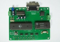
MCU board to experiment with the CAN bus.Circuit based on ATmega8515, SJA1000 and PCA82C251 (High Speed CAN). LCD and RS232 may be left off.Can be used to compose and send messages and to receive message. The payload can contain 1 to 8 bytes. 11-bit and 29-bit identifiers are supported. With a little add-on circuit fault-tolrant CAN can be tested too.
MCU board to experiment with the CAN bus.
Circuit based on ATmega8515, SJA1000 and PCA82C251 (High Speed CAN). LCD and RS232 may be left off.
Can be used to compose and send messages and to receive message. The payload can contain 1 to 8 bytes. 11-bit and 29-bit identifiers are supported. With a little add-on circuit fault-tolrant CAN can be tested too.
Cable and connection problems can be detected.
Messages can be relayed to RS232 port.
Software written in BASCOM-AVR. Several versions featuring different functions are available in the attached archive. A description by the author (in Dutch!) is available as well.
Discussie (9 opmerking(en))
555 11 jaar geleden
555 11 jaar geleden
dscn0404.JPG (540kb)
555 11 jaar geleden
Software for cantester with LCD and hyperterminal. (3kb)
555 11 jaar geleden
SW for function 1 boardA and boardB together automatic (boardB) (3kb)
555 11 jaar geleden
555 11 jaar geleden
Functions of the cantester:
For this function you need 2 boards.
BoardA and boardB are sending messages (with11 or 29bit identifiers) to each other.
Every message contains an identifier and 8 databytes (here we use 1 databyte)
BoardA sends messages who are only destined for boardB, and boardB sends messages who are only destined for boardA.
The messages are received the same way, board A receive only the messages of boardB and vice versa.
The transmitted databyte comes on port D of the microcontroller, and is made visible by means of 4 led’s that every 2 go on /off.
The on /off going of the led’s indicates continuous data traffic between the 2 boards. This also means that the wiring (twisted pair ) is correct.
This function is ideal for the cantester for testing the wiring of a canbus network (for example in automotive applications).
Connection can be anywhere in the network wiring.
You can place the 2 boards at the locations where the part of the wiring is, where you want to test the wiring.
Pay attention with the terminating resistors when you are testing the wiring of the can bus network ,each board of the cantester has its own terminating resistor (120Ohm) that can be enabled or disabled..
What can we test: Interruption of the can high.
Interruption of the can low.
Can high and can low reversed.
Can high and can low shorted.
Other problems with the wiring (moisture, connectors)
If these errors occur or are present, the led’s immediately stop flashing, if the error is gone then the led’s are flashing again.
To detect occasional failures you can move the wirings and connectors while looking at the led’s.
The cantester works best in a non active network, then there is no other data than those of the cantester alone.
Connected in an active network, the led’s are flashing slower because there is other traffic on the network.(it may be that the software must be adjusted in function of the network that we are testing).
If the led’s are flashing it means that the messages of the 2 boards are send and received, between the other messages.
The software: for board A = basis elektor ENG A00F_250.
For board B = basis elektor ENG B00F_250.
For this function you need 1 board.
Here we use the LCD screen.
The cantester only receive messages here.
With this function we can show can-messages in human language.
The 2 examples are:
The software shows how by some operations on the received data, you can make this data readable.
This can also be used for diagnosis, if you want to see the value of a sensor during a test drive.
The software for the function “handbrake”: 2012ENGreceiveLCD007.
The software for the function “milage” : 501hugochcanENGfil kmstand longLCD.
For this function you need 1 board.
The cantester has a max232, so we can communicate to a PC.
The cantester receives only messages here.
The received data can thus be viewed on the PC and stored (via the program hyperterminal)
This allows all messages or only those you wish to see.
The software for this function: 501hugochcanENGfil kmstand longLCD.(also contains hyperterminal).
For this function you need 2 boards.
Both boards (A and B) can receive and send messages.
Each board has 4 pushbuttons, 4 led’s and 4 jumpers.
Jumper 3 and 4 are set for the pushbuttons and jumper 1 and 2 for the led’s.
We use S3 as pushbutton.
Board A: by pressing push button S3 is a message sent , the ID = 0C1F134A(H) and databyte 1 = alternately 0C(H) and 30(H).
Board B: by pressing push button S3 is a message sent , the ID = 0C1F1315(H) and databyte 1 = alternately 0C(H) and 30(H).
Databyte 1 is put on portD of the microcontroller, this make the led’s blink.
Board A accepts only the data from board B and vice versa.
Simulating messages can also, you can send messages by one board and receive them by the other board.
You can show this messages via the LCD or hyperterminal, or you can drive the led’s by these messages.
555 11 jaar geleden
555 11 jaar geleden
555 11 jaar geleden
555 12 jaar geleden
DE517587 12 jaar geleden