command for step motor to be placed on X axis of a lathe

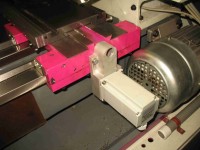
I have a little lathe without cross gearbox. The X-axis must thus be moved manually. I want to place a step motor on the X-axis and create a circuitry (electronic multiplier) for proportional driving of this X-axis relatively to the motion of the-Z axis.
I have a little lathe without cross gearbox (there is only one leadscrew). The X-axis must thus be moved manually. I want to place a step motor on the X-axis and create a circuitry for proportional driving of this X-axis relatively to the motion of the-Z axis. The proportionality factor (relation between the X-axis speed and the Z-axis speed), must to be adjusted with precision and stay stable during turning operation. Example: to turn a piece with conical portion(s). This project needs also to obtain a very precise leadscrew revolution speed information to can drive accurately this circuitry, taking in account that this screw must rotate very slowly !.
Documents are jointed to describe principles to be investigated: (no yet electronics, bud first mechanics !)
- pdf file Elektor project - X-axis by Z-axis control principle EN v6;
- fichier pdf "Projet Elektor - Principe asservissement axe X à l'axe Z FR v6" (version FR du précédent);
- pdf file "looking for an analog solution EN v4";
- pdf file "trails for a digital solution EN".
- Excel file "project numbers summary"
- Excel file "servo parameters v6" (detailled calculi);
Updates van de auteur
Dreyfus 3 jaar geleden
05.01.2021
Following discussion with Clemens Valens, the Arduino DUE microcontroller will be used for the digital solution, in place of Raspberry Pi 3B+.
08.01.2021
Jitter measurements were done on leadscrew speed rotary encoder PMIS4 which generates fréquency F1: there is an enormous jitter on it, so much so that a digital solution should be useless if leadscrew speed information stabilization is not possible !
So, the jitter measured values were approximately 30 % for S1 min (4,1 leadscrew rev/min) and 48 % for 25 % of S1 max (52 leadscrew rev/min). In fact, these measurements were done only with feed selector on min (0,07 mm/spindle rev) !
Remark : jitter definition used : jitter (%) = (T1 max-T1 min) /T1 min.
See 2 screen copies with 1 s display persistence. Attention: on those screens, there is an unit error: that must be V in place of displayed A !
The jitter cause may come from two ways:
a) False interpolations of PMIS4 encoder between poles pairs (there are only 50 pole pairs on the ring and 200 interpolated points between each of them to give 10000 pulses per revolution);
b) And more possible actual speed variations in transmission between spindle and leadscrew through cog-wheels (tooted pulleys which cyclically may take more friction energy with impact on leadscrew – or cyclical backlashes between pulleys with the same effect).
Tests were done with F1 divided by 100 with two SN7490 counters: the results are better bud not yet enough: the jitter measured values falls to 10,2 % for S1 min (4,1 leadscrew rev/min) and to 8,5 % for 25 % of S1 max (52 leadscrew rev/min).
See 2 screen copies with 30 s display persistence.
Other tests must be done to understand the situation:
- divide the frequency by 200 to have the same value than interpolation point number;
- test with spectrum analyser to see how frequency varies;
- test with FM demodulator to see how frequency varies (use of a FVC or DAC ? for ripple analysis);
- test with speed regulated motorized turn table to verify PMIS4 encoder interpolation quality (bud mechanical again and time consuming !).
19.01.2021
New F1 jitter measurements results and interpretation
Jitter measurements were done on encoder frequency F1 and F’1 (F’1 = F1 divided by 200) for full range (4 to 208 rev/min) of leadscrew revolution speed. During measures, the leadscrew was unloaded (bed slide clutch disengaged).
See results on table (jpg file “jitter measurements …… leadscrew” in appendix). A full rotation speed range induces increased values, which far exceeds the 30 % previously measured.
A second series of measure was done with all SN7490’s set to zero on Z pulse (PMIS4 encoder also delivers one pulse per revolution and the poles pair for this Z pulse is at the same place than one of the 50 poles pairs for A and B pulses).
This was done to see if problem come from interpolation between poles pairs or not. The measured values are approximately the same than without reset on each revolution. That will say that interpolation is not the problem.
Tentative to extract quickly the FM modulating frequency from F1 signal was aborted because my “demod” spectrum output gives an inexplicable signal (the same signal as when there is no frequency variation !). Just what I can see is that the FFT on my scope shows an asymmetry of the superimposed curves (persistence 10 s - see photography).
Investigation done on backlash in the transmission shows that, following the feed selector position, spindle may be turned on an angle of between 55° and 70° (before leadscrew rotation when I change the rotation direction (see photography with marks on spindle pulley – D = start point). That corresponds to an angular backlash of 1,6 ° to 5,2 ° on leadscrew !
New jitter measures were done with loaded leadscrew (bed slide clutch engaged), with no result amelioration !
Conclusion: The use of leadscrew to give Z movement reference to the calculator is not pertinent.
Continuation of the project:
I will use the existing Z-axis displacement measuring system to give a Z-movement reference, hopping that bed slide inertia and “elasticities” in driving devices will minimize variations in the speed of travel of the bed slide.
s1-52-rev-p-min-f1-w-persist-1-s-in-v-per-div.png (13kb)
s1-4-rev-p-min-f1-div-by-100-persist-30-s.png (12kb)
s1-52-rev-p-min-f1-div-by-100-persist-30-s.png (12kb)
jitter-measurements-on-full-rotation-speed-domain-unloaded-leadscrew.JPG (46kb)
fft-10-dbm-per-div-for-61-leadscrew-rev-per-min-peak-at-16-dbm.PNG (48kb)
spindle-pulley-after-leadscrew-backlash-tests.jpg (1557kb)