
Control up to 128 relays/motors with RS232/USB or Wirelessly
Some time ago I designed a relay controller board for a Traffic signal controller that had to have the ability to control 16 phases (48 relays) using a DSPIC24F and Microchip I/O port expander IC's on the SPI interface to provide the necessary outputs.
Some time ago I designed a relay controller board for a Traffic signal controller that had to have the ability to control 16 phases (48 relays) using a DSPIC24F and Microchip I/O port expander IC's on the SPI interface to provide the necessary outputs. Later I used the same design to drive 48 motors in a vending machine that was based around a standard Intel PC board to provide the Vending machine control logic and the RS232 COM port to connect to the controller design to drive the selected motor that delivers a chosen item. The Microchip dsPic did a great job, but to surface mount the chip was an impossible task, so professional soldering services had to be used for this task. Having a re-look, it should be possible to redesign the circuit using the much cheaper and easier to handle PIC18F4550 chip or even the 16F690 (If no USB support is required). Instead of just providing a RS232 interface, we can also add Wireless control by adding a Zigbee 2.4GHz wireless transmitter /receiver to the circuit as well as a USB interface.
Using the SPI interface, up to 8 X I/O port expanders can be addressed, allowing for a total of 128 outputs! The design can be used for any application that needs to control many devices from a central point such as a process control Personal Computer or a zigbee coordinator can be added to the control board to allow for remote control.
Adding a Zigbee module to the circuit, could allow for low power end nodes to be used to communicate with the coordinator / controlboard and could be used to switch a specific port on or off. (Depending on its network ID) If zigbee routers with solar cell power supplies are added to the zigbee network excellent distances can be achieved between the end node and the coordinator.
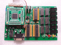
The picture shows the prototype board I used for the vending machine project. (Made a mistake when designing the board layout, so had to resort to good old veroboard to connect the I/O expanders :). The Pic24F will be replaced and additional interfaces added.
Project Scope:
Use the PIC18F4550 to allow a host PC to communicate with a relay/motor controller board using either RS232, USB or join a Zigbee network for remote control. The protype controller will have 2X port expander (MCP23S17) providing 32 outputs. (Up to eight MCP23S17 ICs can be added to provide for more outputs.) The ULN2803 will be used to drive Relays/motors etc.
Mikroe's mikroBasic Pro will be used to program the PIC18F4550.
A separate circuit will be developed to provide the Host computer with a Zigbee connection. The Atmel ATZB-24-A2 chip using the Serialnet AT command set will be used for the Zigbee implementation.
I will also develop a Zigbee router that is powered by rechargeable batteries which will be charged by a solar cell charger should the router be installed outdoors where no direct power is available.
Progress:
I will start with the basics and get the PIC processor communicating on the RS232 and USB ports and test that I can control any of the 32 ports on the prototype from a PC. The circuit will be constructed on Veroboard using iC sockets where necessary. When the above is working, I will add the Zigbee components. The cct. diagram is provisional and may change during the building/testing phases.
But first the power supply. As we are all concerned with green energy, it makes sense to choose a power supply that will perform at a premium. For this reason I used the LM2576HV step-down 'buck' voltage regulator which is about 80-90% efficient as aposed to a normal linear regulator which has a 55% efficiency. After building the power supply I used an old Laptop charger to provide the input voltage of 19V. I then adjusted the output voltage to 5.0V by turning the 50K Pot. The Pot is quite sensitive but to get an exact output of 5.00V proved to be tricky. The closest I could get down to was 5.015V, but this should be fine for the application. The Schottky diode on the output protects the output pin of the LM2576HV step down voltage regulator. When the USB connector is connected to a USB the USB circuitry will also try to power the circuit; the diode will protect the regulator's output pin and prevent too much current from being drawn from the usb circuitry.
The LM1117 3.3V linear regulator has a low drop out voltage, so it is quite happy with 5.3V on its input. As we will not be drawing much current, energy wastage due to heat, will not be too much of a problem.
Photo #1 shows the completed power supply ready to go into a 'Black box'.
The Circuit diagram has changed somewhat. I have added an In circuit programming connection for the PICKIT 3 that will be used for programming the PIC microchip.
Also note that the MCP23S17 has its address hard-wired. In this case, the 23S17 has address 000. the next 23S17 will be wired as 001 etc.
Currently busy soldering the parts together which should be finished by the end of this weekend (10/03/2013)
Protoboard is ready for programming and testing. The Zigbee interface has not been added to the circuit as yet, this will be done when the RS232 and USB interfaces are fully functional. (Photo's #2 & #3)
I also did not add any relay or motors at this stage. Will test the functionality of the 2X8 ports available on the expander with a logic probe to check that they are all responding.
Note thast two pull-down resistors and an 'Error' LED were added to the diagram connecting to RA0,RA1 and RA2 of the PIC processor.
This addition is required to enable the software to detect which interface is currently active. Normally, with no interface connected, both RA1 and RA2 will see a '0' on their inputs. This condition will assume that the Zigbee interface is active.
When the RS232 connection is used, Pins 1,4,and 6 of the 9-pin connector will be high as the 'Terminal Ready' signal from the PC will be +5V as soon as the selected COM port is initialised.
When The USB port is connected, Pin 1 on the USB connector will be +5V.
An error condition occurs when both the USB port and RS232 port are connected simultaneously. This will light the 'Error' LED and the software will ignore all data inputs until the error has been resolved.
Jumper J3 was also added so that we can disable the +5Volt from driving the circuit when a permanent power supply is available. If the circuit is going to be driven by the USB port, the Jumper J3 must be connected, and no external power supply should be connected.
Be careful though, if relays and motors are connected to the output, too much current will be required, which may damage the USB power supply!
17/0313
Tested the RS232 interface and started the coding to allow a user to test the output of the Expander ports. Because the 18F4550 has the same pin (RC7) allocated as RS232 Receive(RX) and the SPI interface SDO signal, I chose to use alternative pins for the RS232 tx and rx lines, requiring that I deal with the RS232 at a software level.
(Hex file attached)
The way to test after loading the Hex file it is to connect the RS232 port to a PC either via COM1/COM2 or by using a USB- RS232 converter which will normally run on COM9 or COM10. Use a program such as Hyper Terminal to establish a connction. Port settings are: 19200bps, 8 data bits 1 stop bit and No parity.
The program expects the following input from the PC:
Val1Val2Val3z where:
Val1 represents the expander address (0 - 8)
Val2 represents the port number (0 - F) where 0 - 7 is GPA 0-7 and 8-F is GPB0-7
Val3 represents the port status 0=OFF, 1 =On. the 'z' character is a terminating character required by the program.
Thus 001z will address Expander 0, PortA0 ON and 000z would switch Expander 0, PortA0 OFF
Now that the RS232 port is functional, and the expander ports can be switched on/off with a simple command, I will connect a zigbee transceiver to the circuit and write the code to achieve the same results from a remote PC. This is somewhat more complicated as the zigbee protocol transmits some extra overhead which will have to be dealt with. Also, in order for the Atmel zigbee unit to communicate, 'Serialnet' needs to be loaded.
To provide the Zigbee implementation for the protoype I proceeded as follows:
First, I added the necessary hardware to the prototype board. As the IC's for this section are all surface mount types, I had to use wires to connect the pins to the rest of the circuit and each other. Doesn't look too great, but it works.
I then built three further circuits:
The first circuit, (CCT diagram #2) is a Zigbee unit that gets connected to the PC via an Rs232 port or USB-RS232 converter.
Note that I used a different Zigbee transceiver here, being the ATZB-A24-UFL. With additional amplifiers, It is rated at being able to achieve a distance of up to one kilometer, which would make an additional router to achieve distance, unneccessary. If a standers ATZB-24-A2 unit is used instead, the distance is about 30-40 meters.
The second circuit (CCT diagram #3) is a router which receives its power from rechargeable batteries. I added a solarcell and simple charger circuit to allow for the batteries to be recharged during daylight, should your router be placed somewhere where no permanent power is available.
The third circuit is a simple Zigbee programmer. (CCT Diagram #4) Instead of using the SN74LVCC3245A, I used the MAX323 circuit. However, instead of powering it with +5Volt, I provide it with +3.3V, wich ensures that the Zigbee transceiver TX and RX signals are within range.
Once the hardware is completed, you need to setup the Zigbee Tranceivers.
First we need to load the 'Meshnetics Serialnet' software that makes it possible to communicate with the zigbee transceiver using AT comands.(similar to the HAYES modem AT commands which were used in the early 80's to configure modems.)
You can download the bootloader from the Atmel web site where it is known as 'Bitcloud'
However, I have added all the necessary files to the 'Zigbee bootloader files.zip'
you should find the following files:
1) Boot loader image - What the bootloader looks like when ready to start loading onto an Atmel Zigbee unit. Note that the unit is connected to COM1.
2) BootloaderOtauSetup_1.2.1.165 - The bootloader installation file
3) jre-6u27-windows-i586-iftw - the Java run time required by the bootloader
4) SerialNet_ZigBit_Rf230.srec - The Serialnet firmware that is loaded by the bootloader so that your Atmel Zigbee unit will understand the 'AT' commands.
Two methods may be used to load the software onto the Atmel ATZB-24-A2 processor: using a JTAG programmer, or via the Rs232 serial port. As the circuit already contains a RS232 PC connection, we can program the ATmel using the RS232 connector.
On the board, disconnect jumpers J1 and J2 so that the PIC is not connected. Now jumper a1 to b1 and a2 to b2.
This will connect the RS232 interface directly to the Atmel Zigbee tranceiver.
Note: PC TX is connected to ATMEL TX (Pin13)
and PC RX is connected to the Atmel RX (Pin14)
Install the Atmel bootloader program on your PC and run it. The following screen is displayed: See bootloader Image
Select file: Serialnet_Zigbit_Rf230.srec file in the 'Select srec file' textbox
Click on the 'Upload' button.
The file will be uploaded.
Once the firmware has been loaded, you can configure the Zigbee unit. Disconnect the bootloader and use a program such as Hyper terminal to communicate with the Atmel device.
At the prompt type: ATX
the Atmel will respond with: OK
You are in bussiness!Now type the following commands:
AT+IPR= 19200 'This sets the speed to 19200bps
If you were working at a different speed when using the bootloader, you will have to reset Hyperterminal and change the speed to 19200, after which you must reconnect.
Continue with the following commands:
AT+GSN=1 'This sets the device's MACaddress to 1. Note that all 'devices must have a unique MAC address.
AT+WROLE = 0 'This command configures the tranceiver as a co-ordinator. 'Note ther can only be one coordinator in a zigbee network
' and you must have one coordinator defined.
AT+WSRC = 0 'Logical unit address. Note 0 is reserved for coordinator.
AT+PANID = 1620 'Sets the channel number. All nodes must have the same PANID 'to be part of the network.
AT+WCHMASK=100000 'Sets the channel mask. All Zigbee nodes must have the same mask in the network
AT+WPWR = 1,10 'Sets the sleep/active durations for power management.
'All nodes must use the same power management settings. In 'the example the device sleeps for 100ms and is awake for '100 milliseconds. Note: Sleep time is expressed in 100ms
'periods whilst wake time is expressed in 10ms periods.)
AT+WAUTONET=1 'This command ensures that the network will automatically be setup and 'that nodes automatically JOIN networks when they are powered up.
ATZ 'Reboot the device
END Node configuration.
=======================
See circuit diagram #2
The Zigbee unit that connects to your PC (via Rs232 or an USB-RS232 converter) must be loaded with Serialnet using the bootloader as described above.) Once you have loaded the firmware configure as follows:
ATX
Speed 19200 (AT+IPR=19200)
Reset Hyperterminal to 19200 to continue...
MAC address: 55 (AT+GSN=55)
Network ID: 55 (AT+WROLE=2 +WSRC=55) Sets as End Node address 55 'Note: WROLE=2 configures the Zigbee unit as an end node.
PANID 1620 (AT+WPANID=1620 +WCHMASK = 100000)
Power Management (AT+WPWR= 1,10) 100ms sleep, 100mS Awake NOTE:
TX Power (AT+WTXPWR=3) +3DBM
DTR: (&D0) Ignore DTR Line
CTS: (AT+IFC=0,2) CTS is used to indicate when ready to Xmit
AUTONET: (AT+WAUTONET=1)
ATZ (Reboot)
Router Configuration:
======================
See circuit diagram #3
The Zigbee unit that acts as a router must be loaded with Serialnet using the bootloader as described above.) Once you have loaded the firmware configure as follows:
ATX
Speed 19200 (AT+IPR= 19200) Reset Hyperterminal to 19200
MAC Address: 5 (AT+GSN = 5)
Network Address: 5 (AT+WROLE = 1 +WSRC= 5) Note WROLE=1 configures Zigbee tranceiver as a router.
PANID 1620: (AT+PANID=1620 WCHMASK=100000)
Power Management: (AT+WPWR = 1,10)
TX Power: (AT+WTXPWR=3) set to +3DBM
Autonet= 1: (AT+WAUTONET=1
ATZ (Reboot)
The Hexfile for the project has been updated to recognize the Zigbee protocol.
When transmitting a port command from the PC to the coordinator the command structure is as follows:
ATD 0 031z (Tansmit 031 to address 0)
What will be received is the following:
DATA 0055,0,3:031z
Indicating that data was received from node 55,using unicasting, 3 bytes long:actual data being 031.
The microprocessor program will ignore the bytes before the colon, and use only the last three bytes received to determine the Expander address, Port number and port state.
AT this time no acknowledgent is transmitted back to the sender, but this could be implemented if required.
Now that two types of data formats could be received by the PIC processor via the RS232 interface, it is important the the program can determine where the data came from. This is achieved by monitoring the power lines of the RS232 port and the USB port, which are connected via a pull-down resistor to RA2 and RA1 respectively.
If an RS232 connection has been made between a PC and the circuit, a +5V signal will be seen on RA2.
If the USB port is connected, +5V will be seen on RA1.
If neither ports are connected, Both RA1 and RA2 will be 0V.
The program will use these states to determine how data is interpreted:
RA1 RA2 DATA FROM: String Received:
0 0 ZIGBEE DATA 0055,0,3:031z
0 1 RS232 031z
1 0 USB 031z
Next will be the USB implementation...
Discussie (0 opmerking(en))