
dc motor driver
a straightforward DC motordriver design, small, smart but efficient. Capable of driving dc motors from 12 to 24 volt, and up to 1000 wattschematis is finished and now for the pcb design.
a straightforward DC motordriver design, small, smart but efficient. Capable of driving dc motors from 12 to 24 volt, and up to 1000 watt
schematis is finished and now for the pcb design.
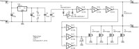
This simple circuit is designed to be used in combination with all kinds of DC-motors. It’s just a simple oscillator driving a bunch of power-mosfets. The oscillator is a basic RC oscillator with a Schmitt-trigger inverter, one from the hex inverter 40106. P1 when turned towards D2 gives maximum voltage to the output. The two diodes prevent short-circuiting the output to the input. In either end position of P1 the charge and discharge times are minimal. In our prototype the negative going pulse is only 1 µs wide and the positive pulse is 1.6 µs. The next two inverters clean up the pulse from the oscillator and drive a buffer stage that’s comprised of three inverters in parallel. R1 was added to prevent the mosfets from becoming conductive in case the 40106 is not in place yet. The total input capacitance of the four mosfets is almost 8 nF. This is too much for the buffer to fully charge and discharge the gate capacitance when P1 turned to its end positions. In practice this means that the motor control is able to regulate the output voltage from 0 to 100 %. The frequency is around 1 kHz. We measured 1.07 kHz on our prototype. D3 at the output suppresses the reverse energy from any inductive load, which all DC motors will have. On our prototype the tracks to D3 were a bit too small and when testing the circuit with one of the motors in a wheely one of the tracks burned out. Each of the motor used in the wheely (there are two of them) draw a maximum current of 20 A at 24 V when maximal loaded. The circuit was tested at 40 A and 24 V with a resistive load. The PCB is not able to handle these high currents. We have soldered 2.5 mm2 copper wires onto the tracks where the large currents flow. Maybe two 1.5 mm2 are better malleable. For this reason the whole PCB does not have solder stop masks. The supply for the 40106 is just a 78L12. Connect the potentiometer by way of small litz wires to the PCB. Best is to mount the heat sink onto the PCB with 3 mm screws. Make sure the heat sink doesn’t come in contact with solder pads from the transistors. Then determine the correct positions of the mounting screws of the transistors and D3. For relieving mechanical stress in the pins of the semiconductors add a little bend in the pins (there are special tools for this) and then locate the positions for the holes and tap 3 mm thread. Don’t forget to insulate all parts on the heatsink. Because of the low switching frequency there’s a change you will hear the 1 kHz emanating from the DC-motor.
Discussie (3 opmerking(en))