
FT232R USB/Serial Bridge/BoB (110553)
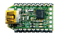
You’ll be surprised by the size of this low-cost, reusable, and multi-platform USB/serial converter the size of a moulded plug on a USB cable!
[Project by Antoine Authier, published in September 2011]
I don’t think much of the various commercially-available FT232R-based modules. Too expensive, too bulky, badly designed, … That’s why I set myself the challenge to design this miniature in the form of a breakout board (BoB). One meaning of breakout is to escape, and in some ways, this board enables all the normally inaccessible signals within complex circuitry to ‘escape’ to the outside world so they can be accessed. Here, the complex circuitry is the legendary FT232R. The very one encapsulated within the plastic of the USB/TTL cables from FTDI. The circuit diagram is based on the information in the FT233R data sheet and makes it possible to produce all the applications described by FTDI (RS-232, RS-485, etc.), along with other ideas (JTAG, BitBang, etc.).
Do not forget to set solder jumper JP1 to define the voltage on VCCIO which in turn determines the levels of the signals. No jumper means that things will probably not work as expected.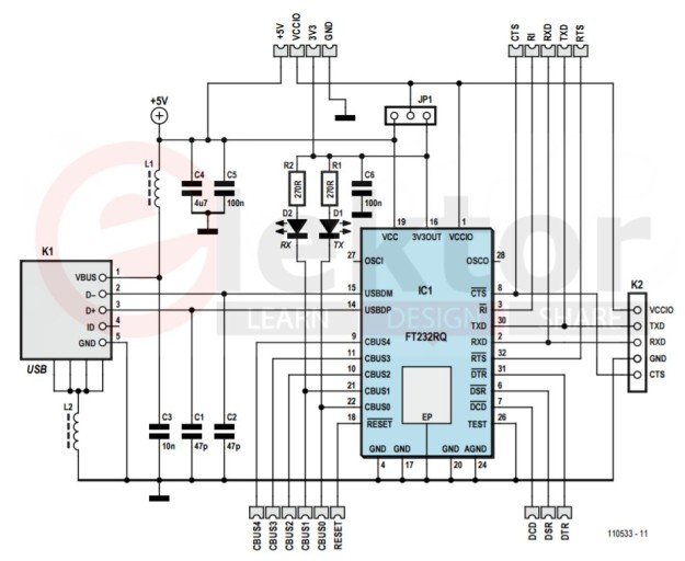
The circuit doesn’t include any fuses, because I’m not sold on polyfuses (resettable chemical fuses) — the only plausible solution here. They reduce the voltage available, which, in my various experiments, dropped below 5 V. I prefer leaving all the voltage and power available to your circuit, which will come in very useful if, for example, you are thinking of including a 5 V/500 mA battery charger further down the line. So it’s up to you to protect your circuit if necessary with fuses or power supply monitors downstream of the bridge.
The 5 V rail comes directly from the USB connector at the front of the board, and offers a maximum of 500 mA for a USB 2.0 port (150 mA for a USB 1.x). The 3.3 V rail is provided by the FT232R: take care not to draw more than 50 mA from it. Above this limit, the only signals you’ll get will be smoke signals.
Then, depending on your needs, you can use a larger pin header, to have access to more signals: the track layout at the rear of the board lets you obtain the equivalent (but not pin-compatible) of an FTDI cable . Along the sides, you’ll find the other signals and the power for the FT232R, accessible via copper contacts on both sides of the board and on the plated edge (!), in the 15.24 mm (0.6”) wide DIP18 format. This way, you can solder two straight pinheaders there and use it within other circuits, on a test board, or plugged into a PCB-mounted socket. You can also solder the bridge board-toboard, piggyback fashion, directly onto the circuit with which you wish to use it. You’ll be able to quickly and easily incorporate this module into your circuit thanks to an EagleCAD library available on the article web page. You’ll also find there a detailed but condensed data sheet — an essential companion when designing and debugging your application.
Find the article & bill of material (BOM) here.
Find the article & bill of material (BOM) here.
I don’t think much of the various commercially-available FT232R-based modules. Too expensive, too bulky, badly designed, … That’s why I set myself the challenge to design this miniature in the form of a breakout board (BoB). One meaning of breakout is to escape, and in some ways, this board enables all the normally inaccessible signals within complex circuitry to ‘escape’ to the outside world so they can be accessed. Here, the complex circuitry is the legendary FT232R. The very one encapsulated within the plastic of the USB/TTL cables from FTDI. The circuit diagram is based on the information in the FT233R data sheet and makes it possible to produce all the applications described by FTDI (RS-232, RS-485, etc.), along with other ideas (JTAG, BitBang, etc.).
Do not forget to set solder jumper JP1 to define the voltage on VCCIO which in turn determines the levels of the signals. No jumper means that things will probably not work as expected.
Circuit description
The ferrite beads protect the circuit against electromagnetic interference from the USB cable. Capacitors C3–C6 decouple the IC power supply. The two LEDs light when data is being transferred over the serial link seen by the module (host). If the device connected to the bridge transmits a byte to it, the RX receive LED lights. Conversely, when a byte is sent from the computer via the bridge, it’s the TX transmit LED that lights.The circuit doesn’t include any fuses, because I’m not sold on polyfuses (resettable chemical fuses) — the only plausible solution here. They reduce the voltage available, which, in my various experiments, dropped below 5 V. I prefer leaving all the voltage and power available to your circuit, which will come in very useful if, for example, you are thinking of including a 5 V/500 mA battery charger further down the line. So it’s up to you to protect your circuit if necessary with fuses or power supply monitors downstream of the bridge.
The 5 V rail comes directly from the USB connector at the front of the board, and offers a maximum of 500 mA for a USB 2.0 port (150 mA for a USB 1.x). The 3.3 V rail is provided by the FT232R: take care not to draw more than 50 mA from it. Above this limit, the only signals you’ll get will be smoke signals.
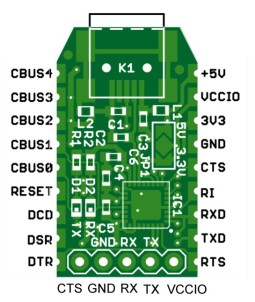
Jumper JP1
Did you notice JP1? It’s the jumper printed on the board, and requires a solder bridge to configure the input/output signal voltages: 3.3 V or 5 V. This needs to be set correctly before using the board: using a tiny blob of solder, connect the central contact to one of the two contacts on either side; the selected voltage is printed on the PCB: 5 V on the USB connector side, 3.3 V on the other. Above all, short only one contact at a time, as only one voltage is possible. Any other configuration would be fatal. The simplest way of using the module consists in soldering a 3-way 2.54 mm (0.1”) pitch pin header to the GND/RX/TX signals opposite the USB connector. In this way you will obtain a USB–UART bridge that is simple, effective, and can be used in almost all circuits.Then, depending on your needs, you can use a larger pin header, to have access to more signals: the track layout at the rear of the board lets you obtain the equivalent (but not pin-compatible) of an FTDI cable . Along the sides, you’ll find the other signals and the power for the FT232R, accessible via copper contacts on both sides of the board and on the plated edge (!), in the 15.24 mm (0.6”) wide DIP18 format. This way, you can solder two straight pinheaders there and use it within other circuits, on a test board, or plugged into a PCB-mounted socket. You can also solder the bridge board-toboard, piggyback fashion, directly onto the circuit with which you wish to use it. You’ll be able to quickly and easily incorporate this module into your circuit thanks to an EagleCAD library available on the article web page. You’ll also find there a detailed but condensed data sheet — an essential companion when designing and debugging your application.
Find the article & bill of material (BOM) here.
Build it or buy it
Even an experienced electronics technician with good eyesight and equipped with suitable tools (in particular, a hot-air soldering iron) will also need to have confirmed masochistic tendencies to set about — and above all pull off — the construction of their own prototype. And those with trembling hands had better steer well clear! The task is so tricky, in fact, that we’re offering (and recommending) the circuit preassembled, ready to use, with the various extension connectors as a bonus.Find the article & bill of material (BOM) here.
Discussie (0 opmerking(en))