
Generating digital communication protocols with the RP2040 PIO
I wrote an Interpreter for the RP2040 PIO. WIth only five types of commands, I can create a sequence of digital signals with exact timing. In the moment I use it to control a digital model railway with a low-priced PICO.
Introduction:
It's not easy to control external logic in real time!
Already in the seventies I used the microprocessor 6502 to realize such projects:
The simple instruction set and the fix instruction execution time (no caches and no speculative memory accesses) allowed the realization. If you have to wait 1us for the sampling instance, take a NOP ...
The state machines of the RP2040 chip open up new vistas for such use cases.
Interpreter:
The interpreter executes following commands:
How to use:
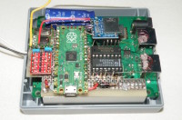
The microcontroller RP2040 is used in many development boards and the MicroPython programming language is available for all exemplares. I took a PICO to control a digital model railway.
What's to do?
The decoders of the locomotives want to receive their commands continuously. So you need a mechanism to restart the DMA.
Now both processors are waiting for a job.
New directives (change speed, switch functions, ...) requires new commands for the interpreter.
An exemplary command sequence is attached.
Test the interpreter:
To try the interpreter, you need a PICO with MicroPython and the Thonny (Python IDE for beginners).
Start the testbench PIO-Interpreter.py and type "help". Now you can see the choices. The PIO is already at work and the output signal can be observed at port GPIO8.
For example
A connected LED flashes every second.
Happy testing!
It's not easy to control external logic in real time!
Already in the seventies I used the microprocessor 6502 to realize such projects:
- Decoding longwave transmitter messages
- Use of cassette recorder for data storage
The simple instruction set and the fix instruction execution time (no caches and no speculative memory accesses) allowed the realization. If you have to wait 1us for the sampling instance, take a NOP ...
The state machines of the RP2040 chip open up new vistas for such use cases.
Interpreter:
The interpreter executes following commands:
- SET0 gives the output "0" for 2, 3, 4, .. 536.870.913us
- SET1 gives the output "1" for 2, 3, 4, .. 536.870.913us
- BTIM defines the baud rate for command DATA in one bit per 2, 3, 4, .. 1.073.741.825us
- DATA gives the output of 1..24 data bits with the in last BTIM selected rate
- NOOP doesn't change the output signal
How to use:
The microcontroller RP2040 is used in many development boards and the MicroPython programming language is available for all exemplares. I took a PICO to control a digital model railway.
What's to do?
- declare a memory region for the sequence of commands
- configure a DMA to transfer the commands to the PIO
- load the interpreter in the instruction memory of the PIO
- configure the PIO (frequency, pins, ...)
The decoders of the locomotives want to receive their commands continuously. So you need a mechanism to restart the DMA.
- configure a second DMA to restart the first DMA permanantly
- load some commands in the memory, fill NOOPs in the unused area
- start all peripherals and the configured pins will be stimulated
Now both processors are waiting for a job.
New directives (change speed, switch functions, ...) requires new commands for the interpreter.
An exemplary command sequence is attached.
Test the interpreter:
To try the interpreter, you need a PICO with MicroPython and the Thonny (Python IDE for beginners).
Start the testbench PIO-Interpreter.py and type "help". Now you can see the choices. The PIO is already at work and the output signal can be observed at port GPIO8.
For example
- wcmd -> address=0, value=0x8007A11E # SET0 0,5 sec
- wcmd -> address=1, value=0xA007A11E # SET1 0,5 sec
A connected LED flashes every second.
Happy testing!
Discussie (1 opmerking(en))