I2C/GPIO 24V Interface Card.

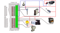
I want to create a Universal 8 X I/O I2C/GPIO 24V Interface Card.The objective is to monitor 8 inputs(24V) and 8 outputs(24V) can be driven. The user can choose between the I2C protocol or 16 GPIO Pins.With the jumpers (SV2, SV3) you choose the I2C protocol.Using a ribbon cable (SV
I want to create a Universal 8 X I/O I2C/GPIO 24V Interface Card.
The objective is to monitor 8 inputs(24V) and 8 outputs(24V) can be driven.
The user can choose between the I2C protocol or 16 GPIO Pins.
- With the jumpers (SV2, SV3) you choose the I2C protocol.
- Using a ribbon cable (SV2, SV3) you can make connection with GPIO-Pins. Without using the PCA9555.
Schematic and a picture to connect sensors and actuators is included.
2013-12-18
First PCB test succeedded.
PCB and schematic update.
2013-10-10Successful 1 Input / 1output hardware test.
Schematic and PCB updated.
Schematic of Test Set-up.
2013-09-16
Output interface test.
2013-08-21
Schematic and PCB created with eagle (not tested).
2013-08-21
Decoupling capacitors placed.
2013-08-15
Optocouplers ILQ615 changed to an ACPL-847.
Resistor R4 changed from 200R to R25 (150R), capacitors deleted.
The 2k2 resistor is split into a R26(1k/250mW) and a R27(1k2/250mW).
Resistor R4 changed from 200R to R25 (150R), capacitors deleted.
The 2k2 resistor is split into a R26(1k/250mW) and a R27(1k2/250mW).
Error found let me know. Thanks in advance.
Home site: http://www.dcisite.be/plux.html#interface (more info).
Discussie (9 opmerking(en))
plux 11 jaar geleden
First successful hardware interface test with 24V and one input and one output.
plux 11 jaar geleden
Testing the 24V output interface.
Have a look at the small demonstration (Author Homepage):
http://www.dcisite.be/plux.interface.html#test24Voutputs
petrus bitbyter 11 jaar geleden
New board layout. Opto couplers corrected. Capacitors added. No way to keep it really single sided as you want the output LEDS near the output connector. As for the board pricing it hardly seems to matter.
petrus bitbyter
petrus bitbyter 11 jaar geleden
plux 11 jaar geleden
petrus bitbyter 11 jaar geleden
Half an eurocard is too small to lay out all those resistors. So I put them upright. Even then the board becomes pretty crowded. No way to get all copper on one side either. So you will need a double sided PCB. As an alternative you can do the top layer traces using thin insulated wire.
There is no decoupling capacitor on the board but they may be needed. At least a 22uF or more near SV1 and a 100nF near the PCA9555D. The 24V also may need some decoupling. I did not add them yet.
Before ordering any PCB's I'd try at least the key parts of the circuit on a breadboard. One can make mistakes. Even if you don't make them yourselves others may have done. It should not be the first time I'd stumble on errors in docs like datasheets.
I zipped the Eagle board design. It was made straight from the schematic that I did not alter. So have a look.
petrus bitbyter
Micclfr 11 jaar geleden
' I have no tools to deal with SMD components and no experience in developing a PCB which include SMD components.'
what is the problem you get with SMd's.
I think the input circuit should look like in the input.sch file i provide.
Micclfr 11 jaar geleden
petrus bitbyter 11 jaar geleden
plux 11 jaar geleden
petrus bitbyter 11 jaar geleden
Made some changes in the input circuit as well. Look at the new schematic.
I added a 1k resistor in the input circuit of the PCA9555. As the input current is in the uA range it will not change the input voltage. (Or only theoretically.) But whenever the I/O-pin is accidentally programmed as an output, it will limit the output current within safe margins.
Looking at Conrads I found another optocoupler, ACPL-847, that's not only cheaper but also better fits in the design.
As for the output circuit, according to the datasheet of the PCA9555, its outputs can source 10mA but the output voltage will drop by a 0.5V. The IR-diode will take a 1,4V. So we will need a 150R resistor (R4) to limit the current. I see no use for the capacitor so I left it out.
At the 24V side we also want 10mA for the LED. As the LED takes 2V and the Vce of the optocoupler is below 1V we can do with a 2k2 resistor as a load. With a Vgs of 10V the IRF540 has enough to fully open so the 2k2 can be split in a 10k/250mW and a 1k2/250mW.
Be aware that the FET switches the low side so the load must be between the drain and the 24V power line. Switching the high side requires some more electronics and, depending on the circuit, maybe a P-channel FET.
Looking for the PCA9555 ME only found SMD-types so far. An alternative may be Microchips MCP23017 but that one is more complicated and requires more programming to initialize. It also comes with some more pins and some possibilities that may be superfluous.
petrus bitbyter
plux 11 jaar geleden
petrus bitbyter 11 jaar geleden
Looking at the datasheet of the TLP291 I found a 10mA diode current sufficient to drive the opto couplers transistor. An ordinary red LED will also light at that current so the LEDs can be concatenated. At 24V a resistor of 2k2/0.5W will set the current for the LEDs. A 1k8 will give a little more current and will also do. If ever the input voltage needs to be changed only this resistor needs to be changed accordingly. In the schematic I divided the resistor in two 0.25W parts. Makes experimenting easier.
The 1N4148 is only there to protect the LEDs whenever the inputs may be accidentally reverse connected.
R3 needs to be raised from 270R to 560R. Otherwise the high input on the PCA9555 wil be on the edge of the specification, so unreliable.
Note that the TLP291 is by no means ideal for this application. It is apparently meant for analog purposes. I also don't know where to buy them though I did not search seriously yet. Finding an opto coupler for digital purposes might be usefull especially when cheaper and easier to get.
petrus bitbyter
plux 11 jaar geleden
petrus bitbyter 11 jaar geleden
Though I have no use for a card like this at the moment I like the idea. But having a glance on the schematic I'm sure it will not work correctly.
Looking at the inputs I see no use for the zener. Having 24V inputs within reasonable margins, simple resistors will do. If you need more then about 10mA per LED you may need 0,5W resistors or use two 0,25W in series or in parallel.
Two non identical LEDs in parallel will not behave. So the signaling LED and the opto-isolator LED need their own resistors. You may however put a third one in series common for both LEDs. Just to divide the total power dissipation.
You can also use any ordinary general purpose Si diodes antiparallel to the LEDs to protect them against reverse connection.
I did not analyse the output circuits but there seems to be something wrong with the opto couplers :(
I do not understand the remark of using no SMD resistors to configure the supply voltage. What resistors should be used to configure which power supply?
As you will have quite a lot of components on the PCB, SMDs may be a good way of keeping the board measurements within practical limits.
petrus bitbyter
Inspiration for the input interface I found at:
http://en.gnublin.org/index.php/GNUBLIN_Module-Rail-Input
Sorry, the optocouplers for the output interface are mirrored. => Fixed.
I do not understand the remark of using no SMD resistors to configure the supply voltage. What resistors should be used to configure which power supply?
Changing the value for R1 ... R32, and you can easily configure a different voltage for the input/output interface.
Regards,
Ivo
plux 11 jaar geleden
ClemensValens 11 jaar geleden