
Improved Radiation Meter [110538] - Hardware Update v2.2
Measure radiation with a photodiode, mounted on a separate sensor board. Controller PCB with 2x16 LCD and serial data interface. PC software available
We redesigned the PCB and changed a few things, but only hardware. Software and functionality are still the same. Next an overview of the present v2.2 hardware:
K1 and K2 are 3-pin SIL headers to connect the small sensor PCB to the microcontroller board. Text is added next to both connectors for clarity: +9V and GND.
K3 is now a 6-pin SIL header to connect our new USB-RS232 converter (FT231X BoB, 180537). For more information https://www.elektormagazine.com/labs/remake-110553-usb-rs232-converter-ft232-bob. Only TXD and RXD and ground are connected. Arrows show the direction the signals.
On 2-pin SIL header K4 the AC-coupled signal from the sensor PCB can be found.
K5 is the standard Atmel 6-pin DIL header to reprogram the microcontroller In-System.
K6 is our standard DC barrel jack connector so a +9 VDC AC-adapter can be connected directly.
De led and buzzer signal pulses being received. Push button S1 resets the counter to start a new measurement.
For additional protection a 220 Ω resistor (R12) is placed in series with the A/D-converter input. The power supply of the sensor board is the AC-adapter voltage and the output voltage of the sensor board can be much higher than +5 V.
JFETs in a TO92-package are getting more and more obsolete and a BF245 used in the original design is getting hard to come by. At this moment a BF256B is still available.
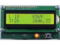
The LCD now used is our preferred green/black LCD with backlight (Elektor shop 120061-74). The backlight can be turned on or off with slide switch S2.
The LCD led and S1 are mounted on the bottom side of the microcontroller board. In our prototype, see photo’s, the LCD is fixed using four 12 mm M3 screws, four round 5x5 mm nylon spacers and four 15 mm steel Female-Female M3 standoffs. But other ways are possible like using 5 mm M3 Male-Female standoffs and nuts instead of nylon spacers. After soldering the components on the top side of both PCBs solder the led and S1 on the bottom side. Then solder the 16-pin header to the LCD first and mount the LCD properly before soldering this pin header to the microcontroller board. If the display is to be used again for other purposes an additional 16-pin socket is also needed; but this places the LCD at a considerable distance from the PCB. Current consumption of the circuit varies between about 16 to 62 mA, depending on falling light on the sensor D1 and backlight turned on or off.
Links:
Original project ‘Improved Radiation Meter (110538)’ on labs
Original article ‘Improved Radiation Meter’
Follow up article ‘Radiation Meter Reloaded’ in issue 10/2012
Kit 110538-71 Improved Radiation Meter
Programmed microcontroller ATmega88PA-PU Improved Radiation Meter
Bare PCB 110538-1 Improved Radiation Meter
USB-RS232 converter (FT231X BoB) - Bare PCB (180537-1)
New USB-RS232 converter project on labs
Bill of materials 110538-1 v2.2
Resistor
R1 = 1 MΩ, 5%, 0.25W, 250V
R2 = 1 kΩ, 5%, 0.25W, 250V
R3, R14 = 10 MΩ, 5%, 0.25W, 250V
R4 = 4.7 kΩ, 5%, 0.25W, 250V
R5, R7 = 10 kΩ, 5%, 0.25W, 250V
R6, R8 = 330 kΩ, 5%, 0.25W, 250V
R9 = 470 Ω, 5%, 0.25W, 250V
R10,R12 = 220 Ω, 5%, 0.25W, 250V
R11 = 100 Ω, 5%, 0.25W, 250V
R13 = 5.6 Ω, 5%, 0.25W, 250V
P1 = 10 kΩ, trimmer, 1 turn, flat
Capacitor
C1,C2,C3,C9 = 100 nF, 50 V, X7R, 5.08 mm pitch
C4,C5 = 47 pF, 50 V, C0G/NP0, 2.5 mm pitch
C6, C7 = 100 µF, 50 V, 3.5 mm pitch, 8x11 mm
C8 = 10 µF, 50 V, 2 mm pitch, 5x11 mm
Semiconductor
D1 = BPW34, 2 pin, top view
D2 = 1N4004, DO41
LED1 = LED 5 mm, Low Power, Red, 20 mA, T-1 3/4
T1 = BF256B, TO92
IC1 = ATMega88PA-PU, DIP28
IC2 = LM358, DIP8
IC3 = 78L05, TO92
Other
Bz1 = Buzzer 12mm, 1-3 Vpp, fres 2.04 kHz, pitch 6.5 mm,
S1 = Switch, tactile, 24 V, 50 mA, 6x6 mm
S2 = Slide Switch, SPDT, On-On, pitch 2.54 mm, 500 mA, right angle (450302014072 Würth Elektronik)
Miscellaneous
K1,K2 = Pin header 1x3, vertical, pitch 2.54 mm
K3 = Pin header 1x6, vertical, pitch 2.54 mm
K4 = Pin header 1x2, vertical, pitch 2.54 mm
K5 = Pin header 2x3, vertical, pitch 2.54 mm
K6 = DC barrel jack, 1.95 mm pin, 12 V, 3 A
IC1 = IC socket, DIP-28, narrow
IC2 = IC socket, DIP-8
LCD1 = LCD Module 2 x 16, Elektor 120061-74
LCD1 = Pinheader 1x16, vertical, pitch 2.54 mm
LCD1 = 4 x Standoff, Steel, M3, Hex, Female-Female, 15 mm
LCD1 = 4 x Spacer, PCB, Round, Nylon 6.6, 5x5 mm
LCD1 = 4 x Machine screw, M3, 12 mm, steel
K1 and K2 are 3-pin SIL headers to connect the small sensor PCB to the microcontroller board. Text is added next to both connectors for clarity: +9V and GND.
K3 is now a 6-pin SIL header to connect our new USB-RS232 converter (FT231X BoB, 180537). For more information https://www.elektormagazine.com/labs/remake-110553-usb-rs232-converter-ft232-bob. Only TXD and RXD and ground are connected. Arrows show the direction the signals.
On 2-pin SIL header K4 the AC-coupled signal from the sensor PCB can be found.
K5 is the standard Atmel 6-pin DIL header to reprogram the microcontroller In-System.
K6 is our standard DC barrel jack connector so a +9 VDC AC-adapter can be connected directly.
De led and buzzer signal pulses being received. Push button S1 resets the counter to start a new measurement.
For additional protection a 220 Ω resistor (R12) is placed in series with the A/D-converter input. The power supply of the sensor board is the AC-adapter voltage and the output voltage of the sensor board can be much higher than +5 V.
JFETs in a TO92-package are getting more and more obsolete and a BF245 used in the original design is getting hard to come by. At this moment a BF256B is still available.
The LCD now used is our preferred green/black LCD with backlight (Elektor shop 120061-74). The backlight can be turned on or off with slide switch S2.
The LCD led and S1 are mounted on the bottom side of the microcontroller board. In our prototype, see photo’s, the LCD is fixed using four 12 mm M3 screws, four round 5x5 mm nylon spacers and four 15 mm steel Female-Female M3 standoffs. But other ways are possible like using 5 mm M3 Male-Female standoffs and nuts instead of nylon spacers. After soldering the components on the top side of both PCBs solder the led and S1 on the bottom side. Then solder the 16-pin header to the LCD first and mount the LCD properly before soldering this pin header to the microcontroller board. If the display is to be used again for other purposes an additional 16-pin socket is also needed; but this places the LCD at a considerable distance from the PCB. Current consumption of the circuit varies between about 16 to 62 mA, depending on falling light on the sensor D1 and backlight turned on or off.
Links:
Original project ‘Improved Radiation Meter (110538)’ on labs
Original article ‘Improved Radiation Meter’
Follow up article ‘Radiation Meter Reloaded’ in issue 10/2012
Kit 110538-71 Improved Radiation Meter
Programmed microcontroller ATmega88PA-PU Improved Radiation Meter
Bare PCB 110538-1 Improved Radiation Meter
USB-RS232 converter (FT231X BoB) - Bare PCB (180537-1)
New USB-RS232 converter project on labs
Bill of materials 110538-1 v2.2
Resistor
R1 = 1 MΩ, 5%, 0.25W, 250V
R2 = 1 kΩ, 5%, 0.25W, 250V
R3, R14 = 10 MΩ, 5%, 0.25W, 250V
R4 = 4.7 kΩ, 5%, 0.25W, 250V
R5, R7 = 10 kΩ, 5%, 0.25W, 250V
R6, R8 = 330 kΩ, 5%, 0.25W, 250V
R9 = 470 Ω, 5%, 0.25W, 250V
R10,R12 = 220 Ω, 5%, 0.25W, 250V
R11 = 100 Ω, 5%, 0.25W, 250V
R13 = 5.6 Ω, 5%, 0.25W, 250V
P1 = 10 kΩ, trimmer, 1 turn, flat
Capacitor
C1,C2,C3,C9 = 100 nF, 50 V, X7R, 5.08 mm pitch
C4,C5 = 47 pF, 50 V, C0G/NP0, 2.5 mm pitch
C6, C7 = 100 µF, 50 V, 3.5 mm pitch, 8x11 mm
C8 = 10 µF, 50 V, 2 mm pitch, 5x11 mm
Semiconductor
D1 = BPW34, 2 pin, top view
D2 = 1N4004, DO41
LED1 = LED 5 mm, Low Power, Red, 20 mA, T-1 3/4
T1 = BF256B, TO92
IC1 = ATMega88PA-PU, DIP28
IC2 = LM358, DIP8
IC3 = 78L05, TO92
Other
Bz1 = Buzzer 12mm, 1-3 Vpp, fres 2.04 kHz, pitch 6.5 mm,
S1 = Switch, tactile, 24 V, 50 mA, 6x6 mm
S2 = Slide Switch, SPDT, On-On, pitch 2.54 mm, 500 mA, right angle (450302014072 Würth Elektronik)
Miscellaneous
K1,K2 = Pin header 1x3, vertical, pitch 2.54 mm
K3 = Pin header 1x6, vertical, pitch 2.54 mm
K4 = Pin header 1x2, vertical, pitch 2.54 mm
K5 = Pin header 2x3, vertical, pitch 2.54 mm
K6 = DC barrel jack, 1.95 mm pin, 12 V, 3 A
IC1 = IC socket, DIP-28, narrow
IC2 = IC socket, DIP-8
LCD1 = LCD Module 2 x 16, Elektor 120061-74
LCD1 = Pinheader 1x16, vertical, pitch 2.54 mm
LCD1 = 4 x Standoff, Steel, M3, Hex, Female-Female, 15 mm
LCD1 = 4 x Spacer, PCB, Round, Nylon 6.6, 5x5 mm
LCD1 = 4 x Machine screw, M3, 12 mm, steel
Discussie (0 opmerking(en))