
IoT at home using MQTT protocol
This project describes an IoT Adapter that allows any electronic device having a serial port to become a MQTT node connected to a WiFi network
INTRO
MQTT is a machine-to-machine (M2M)/"Internet of Things" connectivity protocol, oriented to communication with sensors. MQTT architecture follows a star topology with one or more clients or nodes, and a central server or broker. The communication is based on messages or topics that one node creates, whilst other nodes can receive by subscribing to them. The broker is responsible of managing the network and transmitting messages. The communication can be one to one or one to many.
The aim of this project is to build an IoT Adapter that allows any Generic Device without WiFi capability to become an IoT node. The only requirement is to have a serial port.
To complete a minimal system, we will also discuss how to implement a broker.
The node will be based on an ESP-03 module, while the broker will be implemented on a Raspberry Pi.
See on Image 1 a block diagram including all the elements involved.
MQTT protocol
Let's imagine an office. There is a need to connect several devices with a central unit (thermostats, alarms), or different devices together (lamp with switch). We need a communication protocol, common to all of them.
Among the multitude of existing protocols, MQTT has been chosen for the following reasons:
This protocol relies on the following concepts [1]:
Continuing the example, the air conditioner will also be subscribed to the topic "Floor3/Room2/AirConditioner" This topic will accept two values, ON and OFF. Anyone who publishes the topic "Floor3/Room2/AirConditioner = ON" will turn on the device. Both the maintenance office and a remote command on the room itself will be able to publish this topic.
At this point, do not panic. MQTT provides a lot of options to make it completely secure [3].
Broker
It is a piece of software that must always be aware to the topics published by any device, to then distribute to all those who have been subscribed to that topic.
Among the entire brokers available, we have chosen Mosquitto for the following reasons:
The first thing to do is to install Mosquitto on a Raspberry pi [4].
Open a console and type:
To verify proper operation, the installation provides us a couple of very useful programs: a publisher and a subscriber.
We subscribe to the topic "test" by typing:
IoT Adapter
Basic requirements are that our adapter must be connected to a network wirelessly (as it can be installed anywhere under coverage) and to be low cost (as likely we will install many nodes).
As the core of our IoT Adapter, we have chosen an ESP-03 device, based on the popular ESP8266 chip, for the following reasons:
Thanks to its unique features, the IoT Adapter is merely an ESP-03 with some wires soldered to make it compatible with 2.54 connectors.
Hardware
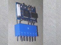
The disadvantage of the ESP-03 is that the pins are not at 2.54 pitch, which prevents plugging to a PCB using a standard connector. Our implemented solution is shown in Image 2. We soldered a wire to each of the necessary pins, bending them so that they are facing a 2.54 header. Maximum care must be taken, trying to use the minimum amount of solder as possible to avoid an irreversible short circuit. This way, the ESP-03 can be plugged and unplugged to be reprogrammed, while the increase of volume caused by the connector is minimal. The vertical position of the ESP-03 helps reduce PCB surface used.
Pins used are the minimum necessary for this application. See in Image 3 the ESP-03 original pinout, and the final arrangement for the IoT Adapter, showing the 12-pin header used.
To program the IoT Adapter we need an USB to serial converter. Bearing in mind that the ESP-03 uses 3.3V (not 5V), Tx and Rx signals must be adapted to these voltage levels. We have used a 5V FTDI cable, so we have made the appropriate level conversions.
The voltage level of signal Rx, going from the FTDI cable to the adapter, must be reduced. We use a two resistor voltage divider. On the other hand, Tx signal going from the adapter to the FTDI cable, must be elevated from 3.3 to 5V. In theory. Actually, it is not necessary because 3.3V is higher than 2.5V, the value that the FTDI cable considers a '1'. See Schematic diagram. The circuit is easily mounted on a breadboard.
Software
What we explain below would also be valid for the ESP-01.
ESP-xx devices incorporate from factory an AT command protocol, too tricky to be used in this project.
A second possibility is to provide them with a LUA language interpreter. MQTT is supported too, and after several tests, it works properly.
A third possibility is to use the widely known Arduino programming environment. As the author is better programming in C++ than LUA, this option has been finally chosen.
Follow these steps [5]:
1. Install the Arduino IDE.
Access to https://www.arduino.cc/en/Main/Software and install the last version.
2. Tell the IDE where to find compatible ESP8266 cards:
Start the Arduino IDE and access the menu File – Preferences
In the Additional Boards Manager URLs box, fill in:
http://arduino.esp8266.com/versions/2.0.0/package_esp8266com_index.json
3. Install compatible ESP8266 card:
Access de menu Tools - Board - Boards Manager… and look for esp8266
Install esp8266 by ESP8266 Community
Select the new appeared menu Tools - Board – Generic ESP8266 Module
4. Install MQTT library:
Access de menu Sketch - Include library - Manage Libraries… and look for mqtt 8266
Install PubSubClient from Nick O'Leary
5. Load and compile the Sketch provided, mqtt.ino
6. Connect the IoT Adapter to the computer as described in the Hardware section, and upload the Sketch. To do this, press the programmer POWER and PROGRAM buttons at the same time (note that the POWER button is a normally closed type). Then release the POWER button and then the PROGRAM button. Thus the ESP-01 is waiting to receive a program. Press the Upload button of the Arduino IDE. After Sketch is sent, press the POWER button momentarily to start the ESP-03 program.
Supplied software performs the following functions:
Communications with the Generic Device are made through the serial port, using a text-based protocol whose syntax is (for both Tx and Rx):
:[Command];[Parameter1];[Parameter2]CRLF
Where:
: Start of line
Command Subscription, status message…
Parameter1
Parameter2 One or two parameters, depending on Command
CRLF ASCII characters 13 and 10 to show end of line
Publish a topic with payload value.
Example:
If a thermostat publish room temperature, it will send:
:publish;Floor3/Room2/Temperature;22.3
:subscribe;topic
Subscribes to a topic.
Example:
An air conditioner will subscribe to a start – stop service:
:subscribe;Floor3/Room2/AirConditioner
As a consequence, it will receive callback commands. See below.
A topic with payload value has been received. Of course, only previously subscribed topics could be received.
Example:
If the air conditioner previously mentioned must be switched off, it will receive:
:callback;Floor3/Room2/AirConditioner;OFF
:status;message
IoT Adapter informs about relevant events to the Generic Device. They are outside the MQTT protocol but retain the same format. Valid values for message are:
Start The ESP-03 program has booted
WiFi_ON Communications with the router has been established
MQTT_ON Communications with the broker has been established
MQTT_ERR Failed attempt to communicate with the broker. Retrying in 5 seconds
Error Unknown Command received
Ping60 Sent every 60 seconds, as a watchdog
Verification
To verify the correct operation of the IoT Adapter, connect the computer serial channel as if we were programming it. Start a serial console on the PC, such as that included in the Arduino IDE. Power up the IoT Adapter module without pressing the PROGRAM button. Program will start, and if everything works correctly the console will show:
Similarly, if we type in the IDE console:
Improvements
A possible improvement might be to add new commands to indicate the router SSID and Password, or the Broker IP address, instead of having them fixed in the code.
This project is intended to help another circuit to become an IoT member, but the ESP-03 has the capability to work as a stand-alone module if the limited number of I/O pins are enough for a particular application. Otherwise, there are equivalent modules with a lot of pins, like the ESP-12.
Applications
Now, we have countless possibilities. Using a standard protocol will allow us to connect with our devices through different applications and from many places.
For example, there are apps for android that will allow us to publish topics or subscribe to them. As we are connected to a network with internet access, and after a little manipulation on the router, we could interact with our IoT devices from anywhere in the world.
Web links
[1] http://thenewstack.io/messaging-reliability-persistence-mqtt
[2] https://mosquitto.org/man/mqtt-7.html
[3] http://www.hivemq.com/blog/introducing-the-mqtt-security-fundamentals
[4] http://www.switchdoc.com/2016/02/tutorial-installing-and-testing-mosquitto-mqtt-on-raspberry-pi/
[5] https://learn.sparkfun.com/tutorials/esp8266-thing-hookup-guide/installing-the-esp8266-arduino-addon
MQTT is a machine-to-machine (M2M)/"Internet of Things" connectivity protocol, oriented to communication with sensors. MQTT architecture follows a star topology with one or more clients or nodes, and a central server or broker. The communication is based on messages or topics that one node creates, whilst other nodes can receive by subscribing to them. The broker is responsible of managing the network and transmitting messages. The communication can be one to one or one to many.
The aim of this project is to build an IoT Adapter that allows any Generic Device without WiFi capability to become an IoT node. The only requirement is to have a serial port.
To complete a minimal system, we will also discuss how to implement a broker.
The node will be based on an ESP-03 module, while the broker will be implemented on a Raspberry Pi.
See on Image 1 a block diagram including all the elements involved.
MQTT protocol
Let's imagine an office. There is a need to connect several devices with a central unit (thermostats, alarms), or different devices together (lamp with switch). We need a communication protocol, common to all of them.
Among the multitude of existing protocols, MQTT has been chosen for the following reasons:
- Open source
- Available for a variety of devices (Arduino, Linux)
- Simple to implement
This protocol relies on the following concepts [1]:
- Any device can publish data, called topic.
- Any device can subscribe to a topic published by others.
- Data is managed by a central unit or server, called broker which is responsible for receiving and distributing data.
- Topics have hierarchical structure, with levels separated by "/" [2]
Continuing the example, the air conditioner will also be subscribed to the topic "Floor3/Room2/AirConditioner" This topic will accept two values, ON and OFF. Anyone who publishes the topic "Floor3/Room2/AirConditioner = ON" will turn on the device. Both the maintenance office and a remote command on the room itself will be able to publish this topic.
At this point, do not panic. MQTT provides a lot of options to make it completely secure [3].
Broker
It is a piece of software that must always be aware to the topics published by any device, to then distribute to all those who have been subscribed to that topic.
Among the entire brokers available, we have chosen Mosquitto for the following reasons:
- Open source
- Easy to install and manage
- Available for Raspberry Pi. Because it has to be in place 24 hours a day, it seems a good idea to use a low power device.
The first thing to do is to install Mosquitto on a Raspberry pi [4].
Open a console and type:
$ sudo apt-get install mosquitto mosquitto-clients python-mosquitto
Now, Mosquitto is installed and running. Also, it starts automatically after shutting down power and starting up again.To verify proper operation, the installation provides us a couple of very useful programs: a publisher and a subscriber.
We subscribe to the topic "test" by typing:
$ mosquitto_sub -d -t test
As the program blocks the terminal, we open another console in another window to publish a message.
$ mosquitto_pub -d -t test -m Hello
In the first window, we see that the subscriber has received the topic.
Client mosqsub/22163-raspberry received PUBLISH (d0, q0, r0, m0, 'test', ... (5 bytes)) Hello
IoT Adapter
Basic requirements are that our adapter must be connected to a network wirelessly (as it can be installed anywhere under coverage) and to be low cost (as likely we will install many nodes).
As the core of our IoT Adapter, we have chosen an ESP-03 device, based on the popular ESP8266 chip, for the following reasons:
- Small size
- Super low-cost
- WiFi communications
- Serial Interface
- Belongs to a large family of easily interchangeable devices
- Friendly programmable by means of Arduino IDE
Thanks to its unique features, the IoT Adapter is merely an ESP-03 with some wires soldered to make it compatible with 2.54 connectors.
Hardware
The disadvantage of the ESP-03 is that the pins are not at 2.54 pitch, which prevents plugging to a PCB using a standard connector. Our implemented solution is shown in Image 2. We soldered a wire to each of the necessary pins, bending them so that they are facing a 2.54 header. Maximum care must be taken, trying to use the minimum amount of solder as possible to avoid an irreversible short circuit. This way, the ESP-03 can be plugged and unplugged to be reprogrammed, while the increase of volume caused by the connector is minimal. The vertical position of the ESP-03 helps reduce PCB surface used.
Pins used are the minimum necessary for this application. See in Image 3 the ESP-03 original pinout, and the final arrangement for the IoT Adapter, showing the 12-pin header used.
To program the IoT Adapter we need an USB to serial converter. Bearing in mind that the ESP-03 uses 3.3V (not 5V), Tx and Rx signals must be adapted to these voltage levels. We have used a 5V FTDI cable, so we have made the appropriate level conversions.
The voltage level of signal Rx, going from the FTDI cable to the adapter, must be reduced. We use a two resistor voltage divider. On the other hand, Tx signal going from the adapter to the FTDI cable, must be elevated from 3.3 to 5V. In theory. Actually, it is not necessary because 3.3V is higher than 2.5V, the value that the FTDI cable considers a '1'. See Schematic diagram. The circuit is easily mounted on a breadboard.
Software
What we explain below would also be valid for the ESP-01.
ESP-xx devices incorporate from factory an AT command protocol, too tricky to be used in this project.
A second possibility is to provide them with a LUA language interpreter. MQTT is supported too, and after several tests, it works properly.
A third possibility is to use the widely known Arduino programming environment. As the author is better programming in C++ than LUA, this option has been finally chosen.
Follow these steps [5]:
1. Install the Arduino IDE.
Access to https://www.arduino.cc/en/Main/Software and install the last version.
2. Tell the IDE where to find compatible ESP8266 cards:
Start the Arduino IDE and access the menu File – Preferences
In the Additional Boards Manager URLs box, fill in:
http://arduino.esp8266.com/versions/2.0.0/package_esp8266com_index.json
3. Install compatible ESP8266 card:
Access de menu Tools - Board - Boards Manager… and look for esp8266
Install esp8266 by ESP8266 Community
Select the new appeared menu Tools - Board – Generic ESP8266 Module
4. Install MQTT library:
Access de menu Sketch - Include library - Manage Libraries… and look for mqtt 8266
Install PubSubClient from Nick O'Leary
5. Load and compile the Sketch provided, mqtt.ino
6. Connect the IoT Adapter to the computer as described in the Hardware section, and upload the Sketch. To do this, press the programmer POWER and PROGRAM buttons at the same time (note that the POWER button is a normally closed type). Then release the POWER button and then the PROGRAM button. Thus the ESP-01 is waiting to receive a program. Press the Upload button of the Arduino IDE. After Sketch is sent, press the POWER button momentarily to start the ESP-03 program.
Supplied software performs the following functions:
- After startup, connects to the router whose SSID and password appear in the code
- Then, tries to establish communication with the broker whose IP address appears in the code
- Waits for receiving subscriptions coming from the network, and for publishing topics coming from the serial port.
Communications with the Generic Device are made through the serial port, using a text-based protocol whose syntax is (for both Tx and Rx):
:[Command];[Parameter1];[Parameter2]CRLF
Where:
: Start of line
Command Subscription, status message…
Parameter1
Parameter2 One or two parameters, depending on Command
CRLF ASCII characters 13 and 10 to show end of line
- Commands from Generic Device to IoT Adapter are:
Publish a topic with payload value.
Example:
If a thermostat publish room temperature, it will send:
:publish;Floor3/Room2/Temperature;22.3
:subscribe;topic
Subscribes to a topic.
Example:
An air conditioner will subscribe to a start – stop service:
:subscribe;Floor3/Room2/AirConditioner
As a consequence, it will receive callback commands. See below.
- Commands from IoT Adapter to Generic Device are:
A topic with payload value has been received. Of course, only previously subscribed topics could be received.
Example:
If the air conditioner previously mentioned must be switched off, it will receive:
:callback;Floor3/Room2/AirConditioner;OFF
:status;message
IoT Adapter informs about relevant events to the Generic Device. They are outside the MQTT protocol but retain the same format. Valid values for message are:
Start The ESP-03 program has booted
WiFi_ON Communications with the router has been established
MQTT_ON Communications with the broker has been established
MQTT_ERR Failed attempt to communicate with the broker. Retrying in 5 seconds
Error Unknown Command received
Ping60 Sent every 60 seconds, as a watchdog
Verification
To verify the correct operation of the IoT Adapter, connect the computer serial channel as if we were programming it. Start a serial console on the PC, such as that included in the Arduino IDE. Power up the IoT Adapter module without pressing the PROGRAM button. Program will start, and if everything works correctly the console will show:
:status;Start :status;WiFi_ON :status;MQTT_ON
We can verify that the module receives orders by the serial port typing an invalid command:
:aaa
The module will respond:
:status;Error
Now we start the subscriber in the Raspberry Pi typing:
$ mosquitto_sub -d -t test
If we type in the IDE console:
:publish;test;Hello
in the Raspberry Pi console appears the confirmation that the message has been posted.Similarly, if we type in the IDE console:
:subscribe;mytopic
And in the Raspberry pi we type:
$ mosquitto_pub -d -t mytopic -m mymessage
in the IDE console appears:
:callback;mytopic;mymessage
Improvements
A possible improvement might be to add new commands to indicate the router SSID and Password, or the Broker IP address, instead of having them fixed in the code.
This project is intended to help another circuit to become an IoT member, but the ESP-03 has the capability to work as a stand-alone module if the limited number of I/O pins are enough for a particular application. Otherwise, there are equivalent modules with a lot of pins, like the ESP-12.
Applications
Now, we have countless possibilities. Using a standard protocol will allow us to connect with our devices through different applications and from many places.
For example, there are apps for android that will allow us to publish topics or subscribe to them. As we are connected to a network with internet access, and after a little manipulation on the router, we could interact with our IoT devices from anywhere in the world.
Web links
[1] http://thenewstack.io/messaging-reliability-persistence-mqtt
[2] https://mosquitto.org/man/mqtt-7.html
[3] http://www.hivemq.com/blog/introducing-the-mqtt-security-fundamentals
[4] http://www.switchdoc.com/2016/02/tutorial-installing-and-testing-mosquitto-mqtt-on-raspberry-pi/
[5] https://learn.sparkfun.com/tutorials/esp8266-thing-hookup-guide/installing-the-esp8266-arduino-addon
Want to build a project?
Bring your design to life with the Elektor PCB Service, powered by Eurocircuits. Upload the project files and order professionally manufactured PCBs or assembled boards through a proven European production platform.
Supporting KiCad, Eagle, Gerber, and ODB++ formats, the service is suitable for everything from prototypes and validation builds to series production and volume manufacturing.
Made in Europe. Fast. Reliable. Professional.
Discussie (3 opmerking(en))