
IoT Based Motion Detection System with ESP32
Are you sick and tired of relying on cumbersome gear and complicated wiring in conventional motion detection systems? So it's time to update to an ESP32-based IoTs motion detection system!
Are you sick and tired of relying on cumbersome gear and complicated wiring in conventional motion detection systems? So it's time to update to an ESP32-based IoTs motion detection system! With the help of this project, you can build a sophisticated motion detection system that is simple to deploy and manage from any location in the world.
You can integrate other devices to increase the system's functionality and even get real-time warnings using the power of IoT technology. Also, you can modify the system to meet your needs and preferences thanks to the advanced features of the ESP32. In this project, I'll walk you through every step of creating your own IoT-based motion detection system with an ESP32. So, prepare for an exciting DIY trip and enjoy IoT technology's ease and innovation like never before!
Components
ESP32 Development Board
The ESP32 development board is a high-performance microcontroller board based on the ESP32 chipset. It is a great option for IoT applications because it has built-in Wi-Fi and Bluetooth connectivity. In addition, the Arduino IDE may be used to program the ESP32 board, making creating and testing IoT-based solutions simple.
HC-SR501 PIR Sensor Module
The HC-SR501 passive infrared (PIR) sensor module can locate people or monitor their behavior. It is often used in IoT projects for motion detection applications.
The PIR sensor module analyses the sensor's data using a pyroelectric sensor, a lens, and electronics. When an object enters the sensor's detecting range, like a human body, it detects a change in the infrared light it produces. This change in radiation is detected by the module's pyroelectric sensor, which the electronics in the module then process.
The ESP32 microcontroller with the HC-SR501 PIR sensor module can be used to create an IoT-based motion detection system. Using its built-in A/D converter, the ESP32 may take action based on the sensor module's output signal, such as turning on a light or sending a notification to a smartphone.
When motion is detected, the ESP32 can be programmed to communicate with other IoT devices, such as a home automation system, and trigger events.
Breadboard
An electronic project prototyping board is called a breadboard. Electronic circuits may be easily tested and experimented with without soldering. The ESP32 board, PIR sensor, and other parts are all linked up on the breadboard for this experiment.
Working Principle
Here’s the working principle for this project:
Circuit Diagram
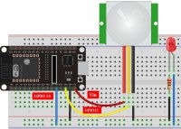
The circuit diagram for this project is shown below: The diagram links a PIR sensor and an LED to an ESP32 board. Three pins make up the PIR sensor: VCC (5V), GND, and OUT (output). The VCC and GND pins are connected to the ESP32's 5V and GND pins, respectively. A jumper wire connects OUT on the ESP32 to GPIO14.
The LED has an anode (+) and a cathode (-). Using a 220-ohm resistor and a jumper wire, the anode pin of the ESP32 is connected to GPIO2. A second jumper wire links the ESP32's cathode pin to the GND pin.
The ESP32 board can be programmed and powered by plugging its micro USB connector into a computer.
Testing the Project
When testing the project, you have to follow these steps:
You've completed the project's testing if everything performs as anticipated. Congratulations!
Conclusion
IoT technology can be utilized for security and surveillance, as demonstrated by the ESP32-based IoT motion-detecting gadget. You can quickly prototype and test your system with an ESP32 board, HC-SR501 PIR sensor module, breadboard, jumper wires, and USB cable. The ESP32 board manages the gadget, and the PIR sensor detects movement inside of its detection range. Making and testing new electrical circuits is a breeze with the help of a breadboard and some jumper wires.
You can integrate other devices to increase the system's functionality and even get real-time warnings using the power of IoT technology. Also, you can modify the system to meet your needs and preferences thanks to the advanced features of the ESP32. In this project, I'll walk you through every step of creating your own IoT-based motion detection system with an ESP32. So, prepare for an exciting DIY trip and enjoy IoT technology's ease and innovation like never before!
Components
- ESP32 development board
- HC-SR501 PIR sensor module
- LED
- 220-ohm resistor
- Breadboard
- Jumper wires
- Micro USB cable
- Laptop or PC with Arduino IDE installed
ESP32 Development Board
The ESP32 development board is a high-performance microcontroller board based on the ESP32 chipset. It is a great option for IoT applications because it has built-in Wi-Fi and Bluetooth connectivity. In addition, the Arduino IDE may be used to program the ESP32 board, making creating and testing IoT-based solutions simple.
HC-SR501 PIR Sensor Module
The HC-SR501 passive infrared (PIR) sensor module can locate people or monitor their behavior. It is often used in IoT projects for motion detection applications.
The PIR sensor module analyses the sensor's data using a pyroelectric sensor, a lens, and electronics. When an object enters the sensor's detecting range, like a human body, it detects a change in the infrared light it produces. This change in radiation is detected by the module's pyroelectric sensor, which the electronics in the module then process.
The ESP32 microcontroller with the HC-SR501 PIR sensor module can be used to create an IoT-based motion detection system. Using its built-in A/D converter, the ESP32 may take action based on the sensor module's output signal, such as turning on a light or sending a notification to a smartphone.
When motion is detected, the ESP32 can be programmed to communicate with other IoT devices, such as a home automation system, and trigger events.
Breadboard
An electronic project prototyping board is called a breadboard. Electronic circuits may be easily tested and experimented with without soldering. The ESP32 board, PIR sensor, and other parts are all linked up on the breadboard for this experiment.
Working Principle
Here’s the working principle for this project:
- The PIR sensor detects any infrared radiation emitted by moving objects in its range of view. Both the sensitivity and the delay duration are controlled using potentiometers. The sensor's sensitivity can be adjusted with the potentiometer, and its delay time can be set with the slider after detecting motion.
- One of the GPIO pins on the ESP32 board is used to connect to the PIR sensor's output. According to the signal, the motion has been detected when the output is HIGH. The output will be LOW in the absence of any motion being seen.
- When motion is detected, the ESP32 board utilizes an LED attached to another GPIO pin to display a message. In addition, the SMTP protocol also sends an email notification to a specified recipient. "Motion Detected!" is the email's subject line, which also contains the time and date of the moment.
- The ESP32 chip also produces a web server that can be accessed by any device connected to the same network. The server will load a simple webpage with a message indicating whether or not motion has been detected.
Circuit Diagram
The circuit diagram for this project is shown below: The diagram links a PIR sensor and an LED to an ESP32 board. Three pins make up the PIR sensor: VCC (5V), GND, and OUT (output). The VCC and GND pins are connected to the ESP32's 5V and GND pins, respectively. A jumper wire connects OUT on the ESP32 to GPIO14.
The LED has an anode (+) and a cathode (-). Using a 220-ohm resistor and a jumper wire, the anode pin of the ESP32 is connected to GPIO2. A second jumper wire links the ESP32's cathode pin to the GND pin.
The ESP32 board can be programmed and powered by plugging its micro USB connector into a computer.
Testing the Project
When testing the project, you have to follow these steps:
- Connect the ESP32 board to your laptop or PC using a micro USB cable.
- Open the Arduino IDE, and then from the Tools option, choose the appropriate board and port.
- Change the WiFi credentials and email parameters in the code to your values.
- Compile and send the code to the ESP32 board using the send button.
- Open the serial monitor, and specify 115200 as the baud rate.
- Keep an eye on the LED and serial monitor output while moving your palm in front of the PIR sensor.
- Check your mailbox for an email from ESP32.
You've completed the project's testing if everything performs as anticipated. Congratulations!
Conclusion
IoT technology can be utilized for security and surveillance, as demonstrated by the ESP32-based IoT motion-detecting gadget. You can quickly prototype and test your system with an ESP32 board, HC-SR501 PIR sensor module, breadboard, jumper wires, and USB cable. The ESP32 board manages the gadget, and the PIR sensor detects movement inside of its detection range. Making and testing new electrical circuits is a breeze with the help of a breadboard and some jumper wires.
Discussie (1 opmerking(en))