
Level and distance gauge with alarm function [140209-I]
This project achieves a measuring instrument with the following functions:
This project achieves a measuring instrument with the following functions:
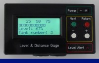
- Measurement of liquid levels
- Level monitoring function with relay output and LED alarm indicator
- Programmable min/max alarm levels
- Storage of min/max calibration values for 10 different containers or tanks
- Distance measurement
- Intuitive menu guidance via LCD display
Many of us are aware of this problem: The lawn mower requires gasoline and we don't know how much petrol in the petrol tank is left. The shake test provides only vague results. Or we want to find out the level of an oil tank or rainwater cistern. Another practical example: We fill a big container with the garden hose with water, but we don’t want to observe this process until the container is full. Here the water supply can be interrupted by a solenoid valve automatically when the desired level is reached. Or you would like to simply gauge the distance between two objects. Read the attached documents and you can realize a low-cost instrument with a high utility value.
Revision 1
English and german documentation corrected
Revision 1.1
English and german documentation expanded
Revision 1.2
Schematic figure for calibrating empty level corrected in english and german documentation
Revision 1.3
Some indefinite descriptions and translation mistakes corrected
Revision 1.4
Bug in menu navigation resolved - new software version added
English and german documentation expanded
Revision 1.5
English and german documentation corrected
Revision 1.6
Component change: Regulator LT 1086 CT-5 replaced with type LM2940CT-5 because of lower dropout voltage.
English and german documentation corrected
Revision 1.7
Code optimization and comments added
Revision 1.8
Code optimization and comments added
Revision 1.9
Hardware change: 2.2 KOhm (R4) resistor added to pulldown the ECHO-port.
Some US-modules need this resistor to work properly.
Circuit diagram, english and german documentation corrected
Revision 2.0
Weblink added to english and german documentation
Revision 2.1
Code correction: If no echo signal should be received an error message will be displayed now.
Revision 2.2
Code correction: If no echo signal should be received the software may hang in a loop when using the module DYP-ME007. To prevent this problem a watchdog logic is implemented now. Does not occur when using module HC-SR04, because this module has a hardware timeout.
Revision 2.3
Code correction: Logic for mode 'Level Watchdog' corrected - was defect since last update. ASCII-value for displaying level as bargraph changed for using lcd MC41605A6WK.
Revision 2.4
Code correction: Software timeout handling for US-modules without hardware timeout corrected.
Want to build a project?
Bring your design to life with the Elektor PCB Service, powered by Eurocircuits. Upload the project files and order professionally manufactured PCBs or assembled boards through a proven European production platform.
Supporting KiCad, Eagle, Gerber, and ODB++ formats, the service is suitable for everything from prototypes and validation builds to series production and volume manufacturing.
Made in Europe. Fast. Reliable. Professional.
Discussie (5 opmerking(en))