
Lost Model Alarm [120139]
There are a number of systems around used to locate lost R/C models. I considered that I could build a system that was a little bit better.
- Lightweight transmitter for the plane;
- Battery backup in case of disconnection of the main batte;
- Using commercial, type approved UHF ISM band radio modules;
- Range at least 600 ft. (20 m);
Receiver to be handheld and able to use radio direction finding (RDF) to locate the model.
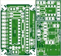
Transmitter PCB, bare, 120139-1
Receiver PCB, bare, 120139-2
Charger PCB, bare, 120139-3
PICAXE-08M2, programmed, 120139-41
Mail from author 15-10-2011:
The project is loosely called a Lost Model Alarm (LOMA) , for RC aeroplanes, but it could be used to locate any device. This project is different to to others around, as it is a complete system and it is very inexpensive. The system consists of a transmitter, using a cheap, readily available 433Mhz (or 355 MHz) transmitting module available from a number of suppliers. There are two versions of the transmitter - one uses a
small lithium battery as a backup, in case the plane's battery is disconnected, and a version without any battery backup. Both versions are driven by a simple PICAXE microcontroller, programmed in PICAXE Basic. The transmitted signal can have its signature changed so that many users can use this system in proximity.
The receiver is based on a complementary 433 MHZ (or 355 MHz) receiver module. The difference in my design is that a signal strength voltage is picked off the recever and displayed on a simple bar graph. With the accompanying 4 element Yagi antennae, the modeller can find the
model by direction finding, since the bargarph will indicate the signal strength and hence the direction. There is also an audio output to a piezo speaker so that one knows that one is chasing ones own plane and not some other signal.
The use of standard receiver and transmitter modules means that not only that they are readily available all over the world, but depending on the country, the correct frequency for the ISM band is also available. There is no need to change the design (except the antennae) for the different frequencies.
The project also includes a design for a 4 element Yagi antennae. It is made from coathanger wires, and for stability it is housed in a small section of corrugated plastic.
The project uses readily available parts. The tranmitter uses a small SMD board, but it is only single sided and the receiver is built on a single sided board as well. This makes it suitable for the DIY person constructing this project. As well, there is only the transmitter microcontroller to program, and the software to download the program is available freely on line.
The schematics are attached. The system has been built and tested. The range is an urban area was more than 250 meters. I will make the code freely available. The article also contains some instructions on how to use Radio Direction Finding (RDF) to search for lost planes.
I can write the article myself (I have a lot of technical wrting and publishing experience) , and your editors would just need to adopt it to the magazines style.
I'm looking forward to your response
Regards
Robert Budniak
Additional material from the LAB:
The transmitter and receiver modules (both from manufacturer Jaycar) used in the original design are difficult to get, at least in this part of the world. They were substituted by types from Quasar. This doesn’t change much for the transmitter circuit.
For the receiver circuit however there’s a bonus. Instead of having to tap a signal from an integrated circuit on the module which is not provided on the standard connections the quasar receiver puts out the RSSI signal and can directly be connected to the display driver. The driver resistor (R1, receiver circuit) for the piezo transducer was increased to 1 kΩ, this reduces the current consumption somewhat. Most current is used by the display driver when a led lights up. Total current consumption is 40 mA (15 mA without a led). The receiver module only uses 6 mA. So with 3 penlights (AA batteries) as a power source the receiver can last more than 3 days continuously (assuming the capacity of an AA alkaline battery is about 3000 mAh with a light load). The piezo transducer (AC) is a small one, only 14 mm in diameter. The resonant frequency is 4.8 kHz and the rated sound level is 85 db. This particular one is not mandatory and any other one will work just as good. It was simply chosen because of its size. We’ve mounted the receiver module vertically on the PCB but if the legs are bent, it can also be mounted parallel underneath the PCB. The antenna, battery and transducer connections on the PCB are all pin headers. Of course wires can also be soldered directly to the PCB. The dimensions of the PCB are 44.22 mm x 30.25 mm.
The PCB for the transmitter is contains only the PICAXE processor (DIP-8), two digital transistors, 2 SMD resistors (bottom side) and 2.54 mm spaced connectors on every side (including the connection for the transmitter module K3). The dimensions of this PCB are only 21.77 mm x 17.78 mm. The transmitter module is even smaller and the 150 mAh single cell Lipo battery slightly bigger. The dimensions of the battery we use are 25,4 mm x 17 mm x 7 mm. But that may vary with other brands and capacity. If necessary a bigger capacity can be used, if the extra space and weight is not a problem. Not all batteries have the standard Molex connector (on bigger batteries with more than one cell this type of connector is used for balancing). That’s why we put a standard 2.54 mm pin header as a connector on the PCB. For a mechanical sturdy connection (especially after a crash of the model plane) we strongly suggest soldering the battery wires directly to the PCB and not use a connector at all. Beware not to short the battery when doing so. By bending the legs of the transmitter module the two PCB’s can be positioned parallel to each other (take care to bend the pins the correct way; otherwise the connections will be mirrored). Place a peace of thick insulating material between the two PCB’s (the sharp endings of the through hole components should not be able to perforate it) to avoid a short circuit as a result of mechanical vibrations or a crash. The serial download pins of the PICAXE processor are made accessible to facilitate ISP programming (K2). This way the processor can be soldered directly to the PCB and avoids having to use a socket. Instead of using the AXE027 PICAXE USB CABLE the well-known FTDI TTL-232R-5V cable can be used, but not without a little extra circuit. The little adapter consists of two inverters from a 74HC04. See schematic 120139-4_adapter_for_ftdi_ttl-232r-5v_schematic_v100.jpg. The two TXD signals need to be inverted to make the FTDI cable work with the PICAXE processor in the PICAXE Programming Editor. A suggestion for adapting the firmware is to tune the modulating frequency closer to the resonant frequency of the piezo transducer used should the sound level not be enough. We used PICAXE Programming Editor 5.5.1 (developed and distributed by Revolution Education Ltd).
The use of a 150 mAh single cell lipo battery compelled us to design a fitting charger. Of course there are single cell chargers commercially available but we designed a charger specifically for this little battery.
The selection of the proper IC was dependent on several criteria. Maybe not everyone knows but the regulation voltage of some lipo batteries is either 4.1 V or 4.2 V. Usually this voltage is not mentioned on the battery itself and you have to look for it in a datasheet or the specifications from the manufacturer. Many IC chargers only have a fixed 4.2 V regulation. It also would be nice if the charger can use a USB port as a power source and is able to charge with only a small current. The need for a minimal number of external components would be nice. Eventually a SO-8 from Maxim was chosen: the MAX1811. It uses an internal FET to deliver the charge current. In principle only two decoupling capacitors and for indicating the connected battery is being charged an additional resistor and led can be connected to a dedicated output. Two inputs control the mode the charger is operating in. One input selects the regulating voltage, 4.1 V or 4.2 V (jumper JP2, SELV). The other input sets the charge current, 100 mA or 500 mA (jumper JP3, SELI). A nice feature of this IC is the ability to precondition a near-dead battery before charging. The enable input (EN) is not used and thus permanently connected to the power supply. The general description in the datasheet states specifically it can be powered from a USB port and can handle input voltages as low as 4.35 V, the minimum of a USB port. With higher input voltages (the MAX1811 can handle 6.5 V maximal) and with the high current set the IC will limit the charge current to keep the die temperature at a maximum of 125 °C. In case only a power source with a higher voltage is available a low-dropout 5V regulator is added (IC2). A jumper selects the input voltage for the MAX1811 (JP1:AUX or USB). Do not connect an input voltage to the regulator if the USB port is selected as input source. The input decoupling of the MAX1811 (C2) is also de decoupling of the output of the regulator. This was done to save space. Cooling of the regulator is done by a copper plain on the back of the PCB. This method has its limitations so when using the regulator (JP1 set to AUX) we advise to use the 100 mA charge current only. D2 is added as a polarity protection. Voltage drop at 100 mA is less than 0.3 V. The reverse voltage is 20 V which should be enough in most conditions. Charge time of our battery (when it’s completely depleted) is probably less than 2 hours. The dimensions of the PCB are 29.84 mm x 20.95 mm. Instead of placing the pin headers for the jumpers wires are also an option, if it’s only for a specific battery. In our case the voltage and current setting don’t need to be selectable. And maybe the power source is a standard mains adaptor so AUX can be selected with a wire. On the model plane a socket will be used to make the battery accessible. So on the charger PCB two wires can be soldered from the output to a plug instead of using a pin header/socket.
We tested the range of the transmitter/receiver combination with two simple 17 cm wires as an antenna. The transmitter was lying on a desk in our office and we went for a walk with the receiver. We are situated in a castle with thick wales and surrounding the caste are also buildings. To be short at a distance of roughly 100 meters we couldn’t get a signal anymore. Later on we build an antenna using a Yagi calculator for VHF/UHF version 2.6.6 (2.6.5?; for Günter Hoch DL6WU Yagis; by John Drew VK5DJ). We entered the data and materials we used. The elements are made of 2.5 mm2 copper wire and the boom is made of a piece of wood of 570 mm x 53 mm x 12 mm (so non-metal). The boom is long and wide enough to hold the receiver PCB and battery holder and there’s even space left at the end to handle the antenna.
BOM Transmitter (120139-1)
Transmitter PCB, bare, 120139-1
Receiver PCB, bare, 120139-2
Charger PCB, bare, 120139-3
PICAXE-08M2, programmed, 120139-41
Want to build a project?
Bring your design to life with the Elektor PCB Service, powered by Eurocircuits. Upload the project files and order professionally manufactured PCBs or assembled boards through a proven European production platform.
Supporting KiCad, Eagle, Gerber, and ODB++ formats, the service is suitable for everything from prototypes and validation builds to series production and volume manufacturing.
Made in Europe. Fast. Reliable. Professional.
Discussie (0 opmerking(en))