
LPC810 as NE555 or as Capacitance Meter
The new LPC810 from NXP is an ARM Cortex-M0+ based microcontroller in an 8-pin DIP package. It is also very cheap, although not as cheap as the NE555 in quantities (I quickly checked AVNET, the NE555 in a DIP8 package seems to cost about 10 dollar cents in volume). The NE555 needs a few external parts to work; the LPC810 has to be programmed, which of course adds to the production costs.
The new LPC810 from NXP is an ARM Cortex-M0+ based microcontroller in an 8-pin DIP package. It is also very cheap, although not as cheap as the NE555 in quantities (I quickly checked AVNET, the NE555 in a DIP8 package seems to cost about 10 dollar cents in volume). The NE555 needs a few external parts to work; the LPC810 has to be programmed, which of course adds to the production costs.
Anyway, I thought it might be fun to see if I can use the LPC810 in a way similar to the NE555, producing a square wave signal of which the frequency is set by an external RC network. The LPC810 does not have an AD converter, but its analog comparator (ACMP) is rather flexible and it should be possible to use one of its inputs to detect both the maximum and minimum values of a voltage over a capacitor that is charged and discharged through a resistor. The ACMP can generate interrupts and has an output that can be connected to any I/O pin, so in theory all I have to do is write an interrupt service routine to use the chip as an RC oscillator.
The ACMP can also trigger the state configurable timer (SCT) so it is probably possible to measure the generated RC frequency and calculate the value of the external capacitor or resistor (if the value of the other part is known).
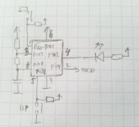
If I use the LPC810 minikit I can wire it up as shown in the schematic. The ISP button can be used for monostable operation, and the LED can show the ACMP output state. The serial port can be used to transmit the result. The RXD input is not available in this setup and should not be connected to the serial port.
Update May 15, 2013
My first experiments went not very well as I managed to brick the LPC800 miniboard :-(. Impossible to get the chip working in ISP mode, so I can no longer program it. I suspect I may have damaged pin 8 (PIO0_0) which serves as RX line for ISP. The capacitor that I connected to it may have done it in.
Luckily I have a second board so I will try (to brick) that one next, but this time with a 100R input protection resistor for pin 8.
The code used in this experiment (v20130515) can be downloaded below.
Update May 16, 2013
After reflection I think the problem was not so much the capacitor as well as the 5V FTDI cable that I used to program the chip in ISP mode. My program reconfigures the PIO0_0 pin as an analog input (fixed-pin function) but the 5V FTDI cable's RX pin was also still connected to this pin and it outputs 5V when it is idle. Reading the LPC800's datasheet I discovered that the analog inputs are limited to 4.6V so this pin may have died because of this. Since I do not have a 3V3 FTDI cable I switched to my LPC812 LPCXpresso board to continue my experiments.
I now have working code that calculates the capacity connected between PIO0_0 and GND based on a charging resistor of 100k (1%). The ACMP ladder reference toggles between to values to create upper and lower bounds for the capacitor charge circuit. The resistor is now driven by PIO0_13 (instead of PIO0_3). The ACMP output is connected to PIO0_7 that has an LED wired to it.
The SCT is so bloody complicated that I finally decided to use it in extreme dumb mode: clear it at the upper capacitor voltage level, then start it and let it run until the cap is discharged enough and reaches the lower level, then read the counter value. All this is done in the ACMP interrupt routine. In the main the capacitance is calculated and the result is transmitted on the serial port.
It works nicely, the code is available below (v20130516). Remember, this is for the LPCXpresso LPC812 board. With a bit of effort it should also run on an LPC800 mini board, but I have to get me a new one first...
Update May 17, 2013
Good news! My pessimistic thoughts about a broken PIO0_0 pin have been proven wrong. It turned out that for some reason the RESET pin had become disabled (I have to examine the code more closely to figure out where and why), making it impossible to get the board into ISP mode by pressing the RESET button. The trick to get out of this tight spot is to remove power from the chip (or the board), then press the ISP button (or ground the ISP enable pin) and keep it pressed (or grounded) when you apply power to the board. Now the chip will enter ISP mode and you are back in control. Once in ISP mode you regain also access to the SWD port and you should be able to use the LPC-Link probe again.
Ah, subtleties like these can make you lose a lot of time and energy :-(
Update May 17, 2013 - 2
I have identified the reason why the RESET pin became disabled. I had used NXP's Switch Matrix Tool to configure the pins, but there appears to be a bug in this tool and it always disables the RESET pin. I used version 2012-11-14, which seems to be the latest even though the download is called version 2012-12-10. So, if you use this tool, make sure that you check its output and especially the line LPC_SWM->PINENABLE0 = <something>; If you want a RESET pin, then bit 6 must be 0, not 1.
Update June 12, 2013
NXP has posted a new version of the Switch Matrix tool on LPCware.com. This version should solve the problem mentioned above.
Discussie (1 opmerking(en))