
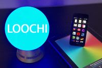
Lumina (was Loochi) - A Bluetooth Low Energy connected lamp [130226]
Lumina is a redesign of Loochi, a BLE-controlled lamp that never made it into production because important parts went obsolete. Lumina fixed this.
Introduction
I started working on Loochi about a year ago. I wanted to build a smarter lamp, one that would use the processing power of a smartphone to move in rythm with the music, simulate a sunset when I am going to sleep or turn itself on automatically when I walk in the room.
After six prototypes, I think this project is ready to become public and I am very happy to share it under open-source licenses for the hardware, the firmware and the mobile application.
I believe it shows how to:
- Build a connected object for the iOS platform using an exciting new protocol (Bluetooth Low Energy)
- Integrate high power LEDs (10W) into a project
- Keep costs down and make the project more interesting by doing in a cheap AVR the work of a dedicated LED current controller
This project also comes with an enclosure that you can 3D print yourself. If you dont have a 3D printer, this is a perfect occasion to visit the MakersLab in your neighborhood or try an online printing service. I hope this opens the door to a new era where every Elektor projects will come with a 3D printable case!
A word on Bluetooth Low Energy
Bluetooth Low Energy is part of the Bluetooth 4 specification. It is designed specifically for simple data exchange between "Bluetooth Smart Ready Devices" (your smartphone, your computer) and "Bluetooth Smart Sensors" (a heart-rate monitoring sensor, a door-knob or a lamp like Loochi).
Bluetooth Low Energy is relatively new and only available in devices manufactured since last year or so (iPhone 4S and +, iPad 3, Samsung Galaxy S3, etc). It is extremely interesting for hobbyists and makers because Apple allows us to develop applications that communicate with Bluetooth Low Energy device without going through the painful (and expensive) "Manufactured for iPhone" (MFI) program.
Before Bluetooth Low Energy, it was almost impossible to use an iPhone to talk to external accessories, which explain why most amateur projects are based on Android phones. This is about to change.
Understanding Loochi schematic
The schematic is available in PDF here and the Eagle files (schematic and board layout) are available on github.
Driving a high power LED
Probably the most important component in Loochi is the RGB led in the center. I chose a 10W led from LED Engin because it seemed to offer the best power to cost compromise. Turns out it provides plenty of light and very rich colours. There are four LEDs in the dice: one red, two greens and one blue. We will connect the two greens in serie and drive them like one.
Driving this type of LED requires a precise current source. We follow the manufacturers recommandation and drive each color at 700mA. The maximum forward voltage for red is 2.96V, 8.32V for the two green leds in series and 4.48V for the blue led.
For this type of power a switched current source is a must have. I chose a buck topology in which the input voltage (9 volts) is hashed at a variable frequency to provide the 700mA current.
The buck converters
The three similar buck converters are immediately visible in the top part of the schema (one for each color). Looking at the red channel (top left), the micro-controller provides a PWM signal (RPWM) which is kept low by the pull-down R7 when the program is not running (not programmed yet or initializing). When the PWM pin goes high, it turns on Q1 through R1 which limits the current on the gate.
When Q1 is on, the current of the LED sinks through L1 and increases progressively; when Q1 is off the inductor discharges through D1 and the LED - the current decreases smoothly.
By controlling the frequency at which Q1 is turned on and the duty cycle, we can reach any average current through the LED. This is how a buck converter works! C1 is just here to help keep the voltage stable.
If we left Q1 on all the time, L1 would charge completely and effectively become a simple wire, the current through the LED would increase indefinitely and the LED would burn (it works: believe me, I tried ;).
If we knew exactly the input voltage of the circuit and the forward voltage of the LED at 700mA, we could use a fixed frequency to control this buck converter. Unfortunately, the forward voltage of the LED will vary for each LED and when the temperature rises, the forward voltage goes down so we need some sort of feedback mechanism.
Sensing the current
R8 is a current-sense resistor of 0.1 ohms. It transforms the current going through the LED and the inductor into a voltage. R4 and C4 form a low-pass filter to average this voltage before feeding it to one of the analog-digital converter of the micro-controller.
Our sense resistor will only see current going through when Q1 is on and L1 is charging but the LED also receives current when Q1 is off and L1 is discharging. The actual current going through the LED is the current measured by R8 multiplied by the inverse of the duty-cycle of our PWM signal.
Still following? This was definitely the most complicated part of this project!
The micro-controller
Now that we understand how the three buck converters work and how we get the feedback signal to adjust the PWM, we can look at the ATtiny micro-controller. I chose this specific model because it includes several differential analog-to-digital converters, a high-speed PWM (with an internal PLL to generate a 64Mhz clock) and does not require much external circuitry to work.
We will use the internal RC-based clock, C7, C8 and C11 are just decoupling capacitors, L4 protects the internal analog circuitry from noise and helps improve the quality of our measures, S1 is an external user button that we will use to turn the lamp on and off without a smartphone. Finally JP1 is the classic AVR programming interface in its 6 pins configurations made popular by Arduino.
The radio
The ATtiny will drive the LED but it needs to know what color to display. This link to the external world is provided by U1, a Bluegiga BLE112 module. This module embeds a bluetooth low energy radio, a micro controller and we will program it through JP2. We are only using a very small subset of its capabilities in this project. The smartphone will send data packets that the module will transmit through an SPI bus to the micro-controller (here, the BLE112 module is the master).
If you dont care for Bluetooth Low Energy, you can build the project without the BLE module and C9, C10, C12 (decoupling caps). The SPI pins are available on JP2 so that you can control the lamp through any SPI master (an Arduino, a Raspberry Pi, a Bluetooth 2 module, a BusPirate, etc).
Powering everything
Finally we turn to the bottom of the schematic to look at the few remaining components. Q4 is used as a polarity protection diode, it has a very low resistance when turned on which means it will heat a lot less than any kind of diode, C15 is a big electrolytic cap to smooth the power supply from the spikes induced by switching the LEDs and R13 helps limit the current when the board is first powered on.
F1 is a small ferrite bead to clean the input voltage before feeding it to U3, a 3.3V linear regulator. C14, C16 and C13 are needed for U3 to work properly as is D4 to make sure the internal circuitry is not damaged if we apply a 3.3V to the VCC rail without powering the board (for example with an AVR programmer). In this scenario D5 guarantees that the current can not flow back to the LED which would probably quickly kill the programmer power supply.
Assembly
I have now built six Loochi v0.6 (the last version, presented here) plus at least a dozen prototypes before. It takes me 4/5 hours to assemble and solder one by hand. I have used modern parts and small SMDs but made sure that it can still be built with a soldering iron and without an oven or some other type of advanced soldering.
You will just need a decent soldering iron, a flux pen, a good pair of tweezers ($3 on mouser.com) and some unsoldering wick. If you have never soldered SMDs before, check out the SMT Soldering Manga, the book by Elektor or the videos on the EEVblog youtube channel. You will see that it is much easier than you think!
Solder the LED
I recommend starting by the LED as soldering it can be quite challenging. It is extremely important that the thermal pad under the LED be very close to the pad on the PCB so that the heat can leave the LED, through the PCB to a heatsink on the other side.
Start by cleaning the PCB and the LED with some isopropyl alcohol, and firmly push the LED on the PCB. Put solder on the tip of your soldering iron and bring it to one of the corner pad. Keep pushing the LED firmly against the PCB. In this version of the PCB, the pads are very large and make this operation a 100% success. On previous boards, the pads were too small and this was extremely difficult.
Once you have two corners, start soldering the other pads. Be careful, if you heat the LED too long not to unsolder the other pads and move the LED. At this point, if the LED moves it will be impossible to get a good thermal contact because of the solder residue on the pads. With a little patience, this is pretty easy.
Make sure the contacts are good with a digital multimeter in continuity test mode. The positive probe goes to the common anode (for example use one of the vias between the led and the power jack), the negative probe goes to each cathode (use the right pad of each inductor). You should see the red led lights up, then the two greens and finally the blue.
Finally flip the board over, and fill all the vias underneath the LED with solder to help spread the heat to the heatsink that we will attach later.
Solder the micro-controller
Next component to solder is the micro-controller. To save space, I have used a MLF32 package. It looks really small but is actually quite easy to solder using the "drag-soldering" technique. Put the component in place, solder one corner and then the other one. Put a lot of flux everywhere, some solder on the tip of your iron and drag accross the pads. Use a magnifying glass to check the pins and if you made a mess just use some solder wick to remove the extra solder. In doubt, apply more flux!
Where we solder resistors, capacitors, etc
With those two components in place, you have done all the hard work. I recommend soldering in this order: all the 0603s (resistors, capacitors, diodes, ferrite bead), the 4 mosfets, the regulator and finally the three inductors, S1 and C15, the electrolytic capacitor.
JP1 and JP2, the two programming connectors are thru-hole. Be careful that the pins are flushed on the other side so that we can glue a large heatsink to the bottom of the board.
Testing the board
It's time to test your new creation! Check the board for any obvious short-circuit, make sure you did not forget to solder one side of the small 0603 parts (it is common to solder one side and miss the other one) and apply a 9V power supply with current limited to 150mA to avoid any serious damage if something is wrong.
Plug an AVR programmer and program the ATtiny micro-controller with the firmware (make program). Do not forget to program the fuses (make fuse) or the program will not work properly. When programming, it is normal for the red led to blink because we are a little short on pins and the red pwm output is also the MISO pin during programming.
Unplug the programmer, allow a little more current (1A should be enough) and press S1, the light should turn on and turn off when you press S1 again. Congratulations!
Now do not let the lamp on for more than a few seconds because we have not attached a heatsink yet!
Add the bluetooth module and finish assembly
Solder the Bluegiga BLE112 module to the board, and program it with the provided firmware and a programmer (Texas Instrument CC programmer - available for $50 from your usual parts provider).
Use double-sided thermal tape to attach the heatsink to the bottom of the board. The thiner, the better. Your heatsink should have a thermal resistance of at most 4~6 °C/W (Lighting Science HS-4075-0345 is a little small but fits perfectly to the board for example).
For more information on heatsinking, I recommend reading the excellent document on thermal management provided by Ledengin.
Finally, if you want a case, use the 3D files provided to get your very own lamp base. There are three different parts that can be assembled very easily and you will need to add a glass shade (IKEA sells one which fits the base miraculously well ;)
Firmware explained
AVR Firmware
The firmware is available on my github account. It is written in AVR Gnu C and includes a Makefile to compile it and program the micro-controller with avrdude.
There are a lot of comments and it should be pretty-much self explanatory so I will just discuss the most interesting points.
We have seen how a feedback loop is formed between the PWM outputs and the ADC inputs. Timer1 is used to generate this PWM which regulates the current to 700mA and runs at 250 kHz with a resolution of 8 bits (256 steps). Initialization for this is in the file current.c.
To produce different complex colors, we mix the red, green and blue with different intensity. This variable intensity is achieved by modulating the current PWM by another PWM at a much slower speed (122 Hz). This second PWM is in the file brightness.c. The values of this PWM are defined by the command received through the SPI ports (serial.c): 3 bytes, one for red, green and blue.
Finally the code that controls the ADC is in the file adc.c. Deciding which channel to measure at a given time is quite complicated: we can't measure a channel if the brightness PWM (the slow one) has turned it off, we need at least two measures before we can trust the ADC reading, and obviously we need to circle between all the channels regularly.
To simplify all this, all the conditions (6) are transformed into bits in a byte and a truth table tells us which channel to read next (function adc_choose_nextchannel()).
For every current PWM value, an expected ADC reading is pre-calculated and stored in a static table. If the ADC reading is below this value, we will increase the PWM, otherwise we will decrease the PWM (function process_adc_reading()).
BLE112 firmware
The firmware for the Bluegiga module is written in BGScript and is extremely simple.
To compile this application, you will need the Bluegiga SDK (available for free on their website but you need to register) and a program called bleupdate.exe (windows only :/ ) to compile and write the firmware to the module.
The iPhone application
The iPhone application is also available on github.
To compile the iPhone application and run it on your device, you need the iOS development kit and a developer account ($99 / year). If you are not interested in modifying the source code, you can send me an email with your UDID and I will send you an email with a link to download the app.
When the application starts, it scans for a BLE112 module programmed with the Loochi firmware and as soon as it detects one, it will show the main menu. From here you can use of the pre-defined effect (cold white, warm white, off), one of the animations (sunset, sunrise, lighthouse, police, etc), manually control the color with your thumb, create your own animation or use the music mode in which the application listens to music around it and controls the light in rythm!
Conclusion
I hope this project can be useful to a lot of people and would love to help anyone interested in building one. Please contact me if you are ready to dive in!
I am also really interested in feedback on this design. Although I spent a lot of time on this, I am in no way a professional electronic engineer and am sure it could be improved in many ways!
Annex 1 - Getting the parts
I have used EuroPCB service and Laen's PCB service (oshpark.com) to get the boards. Both houses gave great quality boards. I tend to favor the purple colored board by oshpark but EuroPCB is much faster.
The full BOM (bill of material) is available on github as well, with parts number for mouser.com. It should not be too hard to find the same parts with other providers.
The 3D files can be downloaded in STL formats from (you guessed it!) github or ordered directly from Shapeways.
Build This Project
Bring this design to life with the Elektor PCB Service, powered by Eurocircuits. Upload the project files and order professionally manufactured PCBs or assembled boards through a proven European production platform.
Supporting KiCad, Eagle, Gerber, and ODB++ formats, the service is suitable for everything from prototypes and validation builds to series production and volume manufacturing.
Made in Europe. Fast. Reliable. Professional.
Discussie (4 opmerking(en))