
Make a Tiny Arduino Drone with FPV Camera
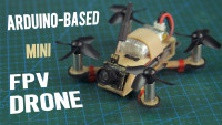
Build a miniature DIY FPV drone that operates fully on Arduino hardware for a fun learning experience and thrilling living room racing.
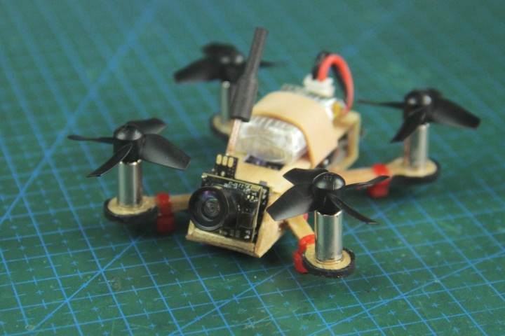
Embark on an exciting journey into the realm of micro-sized flight by making a miniature brushed Arduino FPV drone from scratch. Ideal for the tech-savvy person seeking an engaging challenge, this project ingeniously combines readily available Arduino-compatible modules with a custom motor driver board, all housed in a frame made out of popsicle sticks.
In this blog, we’re putting together a little camera drone that’s configured with MultiWii software and is seamlessly controlled through a DIY transmitter that’s also Arduino-based, making this a fully Arduino-operated drone. Join me as we delve into the intricacies of DIY drone building, finding out what it takes to assemble a compact yet powerful mini quadcopter that promises minutes on end of FPV racing.
Parts and Materials for Drone
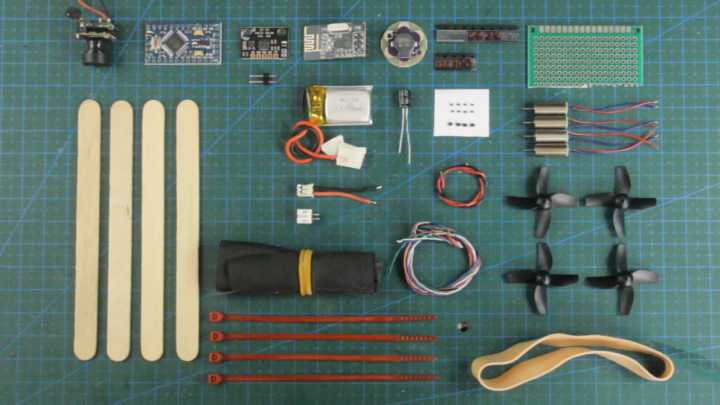
- (x1) Arduino Pro Mini (3.3V) - https://amzn.to/4aL71Nw
- (x1) MPU6050 Sensor - https://amzn.to/4aG87dm / https://www.dfrobot.com/product-2308.html
- (x1) NRF24L01 Transceiver - https://amzn.to/3w2Zpqw
- (x1) Lilypad 5V Buzzer - https://amzn.to/3vPqYna / https://www.dfrobot.com/product-855.html
- (x1) FPV Camera - https://amzn.to/49Mskgn / https://amzn.to/49JtdpH
- (x4) Coreless Motors (6mm) - https://amzn.to/3xL0dkg
- (x4) Propellers - https://amzn.to/3W2VqEU / https://amzn.to/3UppsBn
- (x4) SMD MOSFET (Transistor SI2300) - https://amzn.to/49QQgPn
- (x4) SMD Resistor (10K) - https://amzn.to/4aIgaGw
- (x4) SMD Schottky Diode (SS14) - https://amzn.to/3vXpvuZ
- (x1) Lipo Battery (3.7V 220mAh) - https://amzn.to/3QaLtkR
- (x1) JST Connector - (Salvage from old electronics)
- Silicone wire (24AWG) - https://amzn.to/3TZDate
- Thin wires (30AWG) - https://amzn.to/3UrSdxA
- (x1) Perforated Prototyping Board - https://amzn.to/3W8cSYx
- (x1) Copper Sheet (30x18mm) - https://amzn.to/3w8M6of
- (x4) Popsicle Sticks - https://amzn.to/3UrahHW
- (x1) Rubber Band - https://amzn.to/4aXRB8N
- (x4) Mini Zip Ties - https://amzn.to/49PKsFU
- Bicycle Tube Rubber (Cut piece from old inner tube)
Other Equipment Used With Drone:
- FPV Goggles - https://amzn.to/3QbucrO
- FTDI Converter - https://amzn.to/3Qg5c2H
- Pin Headers for FTDI Connecting cable (use 24AWG wire for cable) - https://amzn.to/3JsoWfL
1. Making a Mini FPV Drone Frame
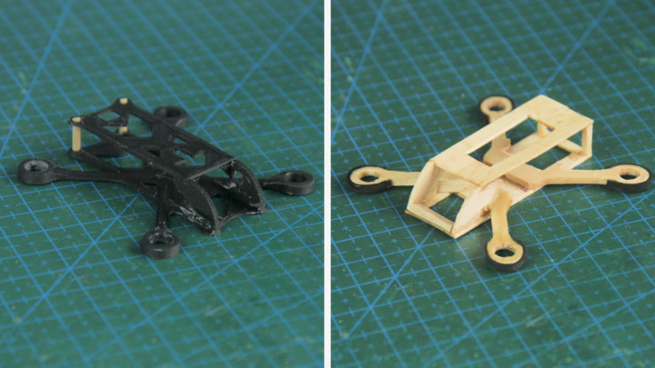
Let’s begin by selecting and making the desired frame for our drone.
The part that will hold all components together is the FPV drone frame. From this tutorial, you have the option to either make it from popsicle sticks with my free parts blueprint for a wooden frame or 3D print your frame through purchasing the 3D model for a plastic frame. Both are just as light (2-3g) and sturdy for the job.
Get The FREE Wooden Frame Parts A4 Sheet blueprint: https://drive.google.com/drive/folders/1qlDlJmhDhmJ9Rr_sS8YcUk7mOFcY7YKy?usp=sharing
Purchase Your Copy of The 3D Printed Mini Drone Frame (3D Model):
https://cults3d.com/en/3d-model/game/mini-fpv-drone-frame-3d-printed-arduino-fpv-drone
To make the popsicle stick drone frame, we'll print out the blueprints sheet for the wood and rubber cutouts which are glued individually onto popsicle sticks with PVC glue stick. Cutting out each piece is as straightforward as scoring the outlines with a hobby knife. Also, we need to soak the most fragile parts in superglue to prevent damage while cutting like the arms which will hold the motors. Additionally, pieces like frame posts can be cut from a matchstick.
After cutting out all of the frame pieces, we'll help reduce the weight of the end frame by sanding down each piece till they're as thin as a credit card except for the four arms which need their original thickness for strength. Once the frame is assembled according to the image, the frame should look like that of one from a larger 5-inch FPV drone. Next, we'll poke a couple of holes for the power connector to protrude.
Looking back at the blueprint sheet, let's take some bicycle inner tube rubber and use the stencils to cut out the drone's bumper guard strips and glue those to the frame. To strengthen the frame even more, we’ll coat the most vulnerable areas with a lick of superglue.
However, if you choose to save time and cut out the fiddly work by instead 3D printing your drone frame, consider purchasing my 3D model of the frame through clicking the link above. Throughout this tutorial however, we’ll stick to using the wooden frame out of the two options to keep the drone more "DIY-friendly" for all.
2. Circuit Diagram
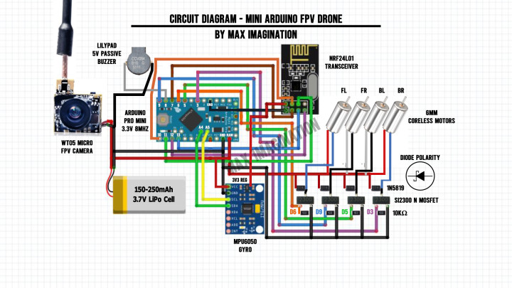
To ensure connections are on-point, following along to the tutorial using the circuit diagram is crucial in succeeding with this Arduino drone.
As we move forward with this guide in working on installing modules, let’s pay close attention to the wiring with every following step in the drone’s circuit assembly, especially taking note of the motor driver circuit.
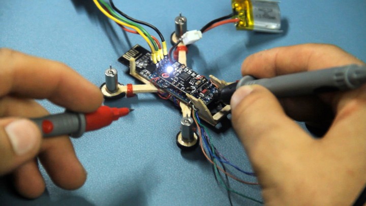
3. Motor Driver Assembly
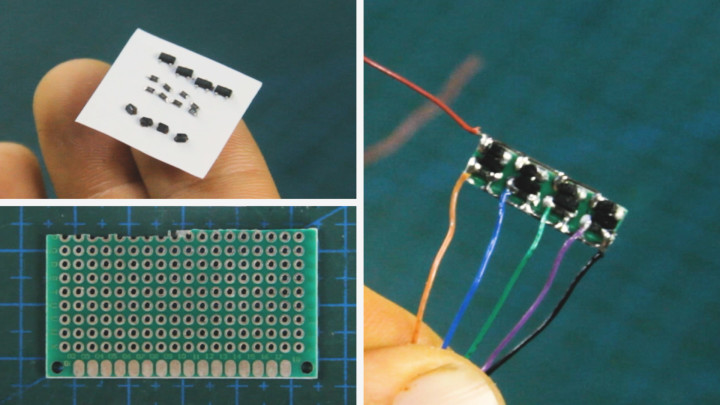
Next up, let's work on making the quad-transistor motor driver board for driving the coreless motors at varied pulses (PWM) without damaging the microcontroller with high currents.
Components to make it can be found in old electronics. I found my resistors and diodes this way. If not salvaged from scrap electronics, the Field Effect Transistors, Diodes, and Resistors can be found linked at the start of this blog.
When dealing with sensitive components like the field-effect transistors (MOSFET) we’re using, let’s be sure to wear an electrostatic discharge wrist strap to prevent zapping them with the built-up static electricity from your body.
We'll start by soldering the N-channel MOSFETs (SI2300 - 3.6A transistor) onto 3 solder pads each, followed by the Schottky flyback (protection) diodes (SS14, 1N5819, or other Schottky diodes) with Anodes to the MOSFET’s Drain pins, and the 10K Ohm pull-down resistors across the lower pins (bridging the Gate and Source pins). We'll finish off by soldering a black wire and line for ground at the bottom connecting all the MOSFTETs’ Source pins to one node and the red wire with power line at the top connecting all the diodes’ remaining Cathode pins together as the power input. Ensuring we use a well-tinned soldering iron, a set of tweezers for component placement, and a set of helping hands or stand to assemble this custom board.
We should end up with 4 sets of each of the 3 SMD or surface mount components soldered tightly on a perforated prototype board - keeping in mind that all components used should match the above values and labels to ensure a properly working motor driver board compatible with the Arduino.
Once all is soldered, let's cut, clip, and sand the little board down to 0.5x6x20mm, reducing its weight and size to no more than 1 gram. We’ll also hook up some colored signal wires to the MOSFETs’ Gate pins. Color is important to differentiate each wire from one another when the board is closed off.
4. Installing Coreless Motors
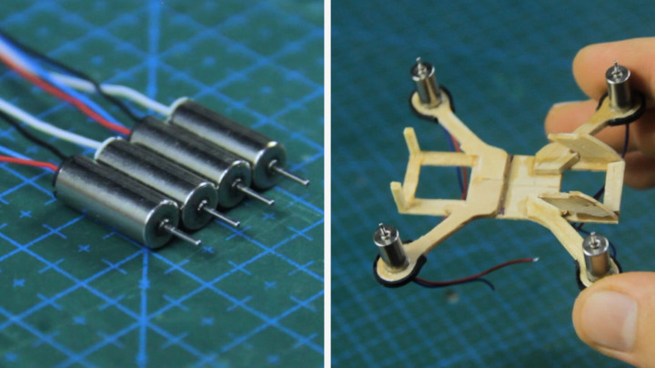
Let's continue the drone's assembly by installing this set of brushed 6x14mm coreless motors into our frame secured with superglue.
Choosing the drone’s motors is an important step that determines whether or not the drone will take off.
We’re using a set of 4 coreless motors designed specifically for mini drones as such that have 2 pairs of clockwise (CC) and counter-clockwise (CCW) motors normally indicated by the red-blue and black-white wire motor pairs. One of these motors with a propeller attached shall produce no less than 12 grams of thrust on its own. 15 grams of thrust per motor is recommended for satisfying flight - an ideal total thrust of 60 grams for the drone to fly well.
See the Motor Thrust-scale Chart here: https://drive.google.com/file/d/1HGZnXKsZlc9eKQ06bKwsCnfFZSF4RB8M/view?usp=sharing
Testing these motors first with matching wire polarity using a battery before installing them helps to ensure proper spinning direction before securing them with glue. Propeller/motor spinning direction is covered in a later step.
5. Connecting and Securing Motor Wires
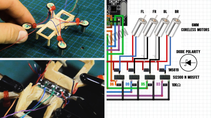
Now comes the wiring of the coreless motors.
We'll begin by first securing the wires with zip ties which also serve as the drone’s feet/landing gear when facing down.
Let’s connect the motor wires directly to each corresponding flyback diode according to the diagram which you can find linked below. The flyback diodes we added earlier that the motors connect to protect the transistors from receiving back EMF currents which could result in frying them as they are sensitive components.
Each motor’s negative wire (blue or black) connects to a MOSFET’s Drain pin or diode’s Anode pin and positive wire (red or white) connects to a diode’s Cathode pin. With a power supply connected to the driver’s supply wires, we can run a quick test to see that each motor runs when pulling the transistors high via applying a voltage of 3.3V to each driver signal wire.
6. Installing Radio Transceiver
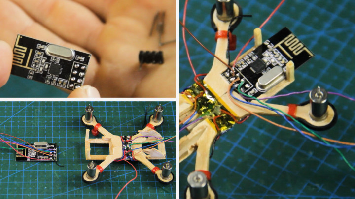
To install our drone’s radio communication module (NRF24L01) which receives data from the transmitter, we’ll begin by desoldering its pins and replacing them for thin wires to both reduce weight and save on space, allowing it to be firmly seated in the frame.
Desoldering its pins is as straightforward as having the module held up by a set of helping hands and using a pair of pliers to pluck one pin at a time while applying heat to the corresponding solder pad above.
With the pins removed, we’ll instead solder colored wires for power, ground, and data to help recognize each wire sticking out when the module’s header is covered.
The radio transceiver can be superglued or simply inserted with a tight fit in the cut out area at the rear of the frame.
7. Making The Flight Controller
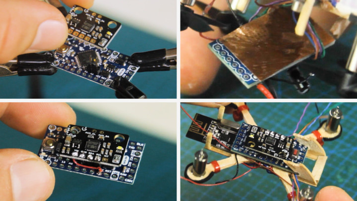
You read that right! We’re making a DIY flight controller for the drone based on an Arduino board and Motion sensor neatly put together in a compact form factor.
We’ll make the flight controller using an Arduino Pro Mini Microcontroller board (3.3V 8mHz version) paired up with the MPU6050 Gyro + Accelerometer motion sensor to determine the drone's orientation in flight. We'll mount and connect it to the Arduino using only a 2-pin header for two-wire (SDA & SCL - I2C) communication and a couple more wires for power. As the motion sensor works with voltage ranges between 3.3V and 5V, it’s recommended to power it directly from the LiPo battery for a consistent power supply.
To prevent the motor driver’s motor-induced EMF currents from affecting sensitive electronics on the flight controller, we’ll cut a sheet of copper or aluminum foil to sit between the flight controller and the motor driver. Let’s ensure this copper sheet is cut to the approximate size of the Arduino Pro Mini and have it taped up with clear tape to prevent short circuits from happening. We’ll scrape a little tape off on an edge and solder a wire for GND. This shield is then glued to the underside of the Pro Mini with a few dabbles of superglue and the grounding wire is then soldered to one of the Pro Mini’s GND pins. Now we have an EMF protective shield for the drone.
Without the shield or sufficient spacing (2+ cm gap - not viable for a tiny drone), the drone is prone to get issues when starting up its motors, causing the Arduino to reset from conflicting induced currents.
Against wires shorting during programming, we'll patch up the radio module's pins with hot glue before sliding in our flight controller which gets secured with a dabble of superglue at the module's crystal oscillator for support.
8. Wiring The Drone
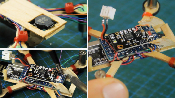
Now, let's finish off installing modules by securing a 5V passive buzzer (Lilypad buzzer desoldered from PCB) with superglue right under the front of the drone so it can indicate its status and the switching of modes via sound. The buzzer’s marked plus (+) pin is wired to the Arduino’s digital pin 8 and the minus (-) pin to GND.
Let's solder a JST connector with wires to the RAW pad (Voltage-In) and GND pad for the battery to power the flight controller.
We'll continue with the wiring of the motor driver and radio transceiver. Starting with wiring the radio module to get powered from the MPU6050’s 3.3V regulator as it has filtering capacitors which works in perfectly reducing the need of additional capacitors. Then, we'll wire the motor driver’s power input wires from the rails we soldered earlier to the power input solder pads where the battery is connected to.
Then, we should have diverted wires going out to the right for driving the motors and wires out at the left of the drone for the radio module's SPI data connection. The NRF24L01’s CE and CSN wires are soldered to Arduino pins 7 and 10, MOSI and MISO to pins 11 and 12, and SCK to pin 13. Google “nrf24l01 pinout” to understand which connections on the radio module I’m referring to or simply follow the diagram.
We’ll then give the FC control of the motors by soldering the motor driver’s four signal wires colored Orange, Blue, Green, & Purple to Arduino pins 6, 9, 5, & 3 - following that order.
Let’s be sure to keep these connections as short as possible while using thin wires (30-gauge electrical wire).
9. Installing The FPV Camera
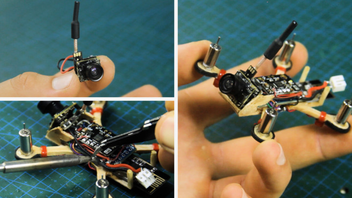
Now, let’s install the drone's FPV camera - a 3-gram, 600TVL resolution First-Person-View (FPV) camera with a built-in video transmitter. We’ll clip off its connector and install the camera in the front of the drone secured with superglue.
The camera should be wired and fed directly from the battery's power (Camera’s voltage input - 3.3-5.5V).
10. Mounting Cover and Propellers
Next, let's close up the drone with its popsicle stick wooden cover.
To assemble and finish the cover piece, let’s secure the JST battery connector with its pins through the two holes made earlier and have the power wires soldered to the pins through the other side while keeping in mind the right wire polarity.
To mount the battery onto the cover piece, instead of velcro straps, we'll secure a piece of a larger rubber band to hold the battery strapped to the top of the drone. After that, we can finally close things up by super gluing it to the 4 posts.
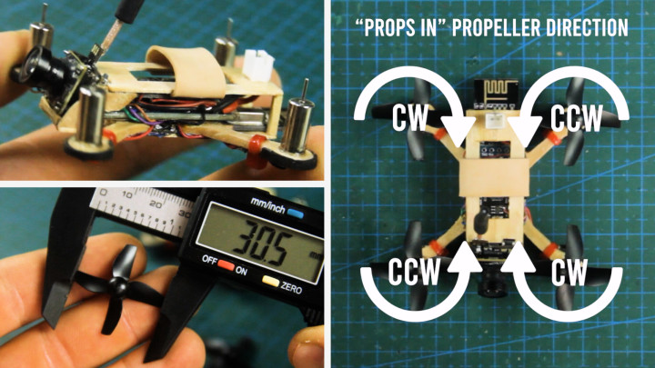
For the propellers, we're using 4-bladed types. The propellers can be two-bladed, but should measure no more than 32mm in diameter for this drone to avoid hitting onboard components. Once mounted with attention to how the blades are oriented, the motors with their propellers of appropriate directions should turn in such a way pushing air downward.
11. Connecting Drone For Programming
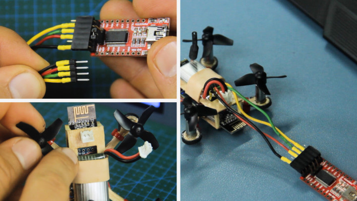
To program the drone, we'll need this module called an FTDI or USB to Serial converter for which we'll make a bridging connector so it can connect to the Arduino Pro Mini in the drone (See product link above).
The bridging connector consists of a 6-pin female header wired to a 4-pin male header for TX, RX, VCC, and GND pins which connects into the back of the drone as seen in the image.
When connected to the drone, the FTDI should have its 3.3-5V jumper for power unplugged - the only source of power to the drone should be from its battery.
12. MultiWii Code
The drone will run on a vastly complex yet versatile Arduino code based on a multicopter software called MultiWii with multiple tabs to manage every onboard drone feature including many other modules that are not used in this drone and overall configuration.
With the drone connected to our PC via the FTDI converter, we can open the code with all of its tabs in the file (code is linked at the bottom of this blog). Credits go to Electronoobs on YouTube for the adapted MultiWii drone code - https://www.youtube.com/watch?v=J0x4ChjUS00&t=961s
In this guide, we will not dive deep into how the code works nor how to set up every pin configuration as this has already been done for you. Assuming you've followed my exact drone wiring, we don't need to change anything related to hardware in the drone’s code. However you'll most likely need to swap around a pair or two of radio channel values if your transmitter's joystick movements appear reversed in the configurator. This can be done in the “NRF24_RX.cpp” tab on lines 84 through 90. In case you want to change the radio transceiver’s CE & CSN pins, go to line 17 in this same tab.
Another change you may need to make is to swap the yaw direction if your drone appears to steer the opposite way. This can be done in “config.h” on line 229 by swapping the yaw direction value from “1” to “-1” or vice versa. “Config.h” also contains so many other configuration parameters for your drone that you’ll have to explore yourself. Read the startup message in the first code tab “MultiWii_RF24” to know where other important parameters can be changed in the code.
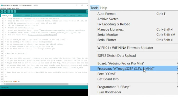
To upload the code to our drone, let's first go to “Tools” and make sure we have the Arduino Pro Mini board selected along with its corresponding processor with matching voltage rating, and your board’s COM port. For a firm data connection, it’s best to hold down the programming connector and hit upload. Just when it reaches the uploading stage, we need to immediately press the Arduino's reset button once and see that it begins uploading code to the board via the writing and reading responses in the terminal.
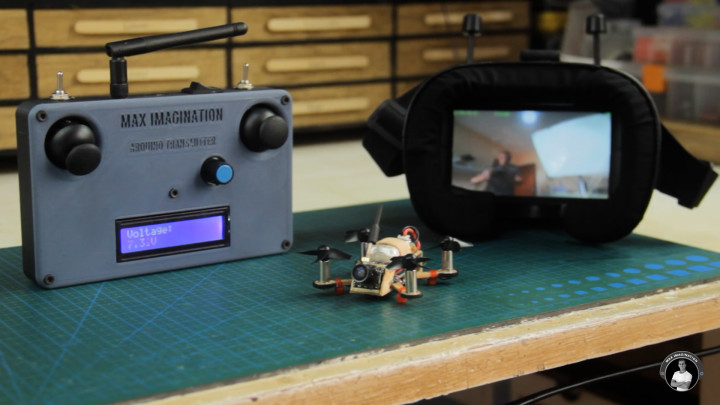
13. Arduino Transmitter
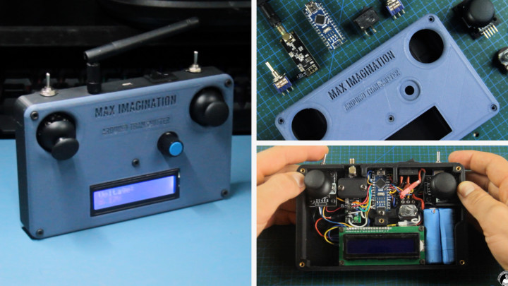
Before we configure the drone in MultiWii, let's have a closer look at the transmitter which will allow us to control it.
I made this 3D printed Arduino transmitter based on the one seen in a YouTube video from the channel “EmiloStuff”, using his transmitter enclosure 3D design with some of my own modifications and added parts such as the two toggle switches, charging port, and voltage divider for monitoring it's voltage to know when its battery is going low. You can find the free modified enclosure design and wiring diagram linked below this blog.
Materials and parts required for Transmitter:
- (x1) Arduino Nano - https://amzn.to/4d6qae3
- (x1) NRF24L01 (Long Antenna) Transceiver - https://amzn.to/4aIzRxI
- (x1) 16x2 LCD With I2C - https://amzn.to/3Qcvweh
- (x2) Joystick Module - https://amzn.to/3vZFwAC
- (x2) Toggle Switch (3-pin) - https://amzn.to/3W5n6cc
- (x1) Potentiometer (100KΩ) - https://amzn.to/3W8MHBg (Optional)
- (x2) 10KΩ resistor (for voltage divider) - https://amzn.to/4dbpAfs
- (x1) Power Switch - https://amzn.to/3Qc9oAz
- (x1) Battery (7.4V 2S) - https://amzn.to/3xF4pSq
- (x1) Power Connector - https://amzn.to/4d7fig7
- (x1) Charging connector - https://amzn.to/447L08U
- Wire (24AWG) - https://amzn.to/3Wdn9D3
- Matte PLA (BLACK) 3D Printer Filament - https://amzn.to/3Q8fhyE
- Matte PLA (DARK GREY) 3D Printer Filament - https://amzn.to/446MXT4
- (x5) M3 Bolts For Enclosure - https://amzn.to/3xH2BbH
- (x5) M3 Threaded Inserts For Enclosure - https://amzn.to/3Ub1p87
See the transmitter’s build video by EmiloStuff here: https://www.youtube.com/watch?v=I6TKGMbHcfo&t=68s
When building our transmitter, including the two toggle switches is important as they will be configured later for arming/disarming the drone and toggling the beeper alarm.
The transmitter’s code that's specifically for controlling our drone can also be found linked below and within it, you'll see where to adjust pin definitions based on your hardware.
14. MultiWii Configurator
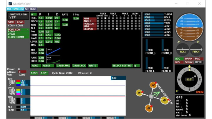
Once we have our transmitter, we can open the multirotor configurator software called MultiWii through opening its folder and selecting the version of this software that corresponds to our computer's operating system. Once the program file is opened, it should look like the image above.
Let's connect to our drone by opening the corresponding COM port it’s on and hitting “Start”. Once connected, we should see the drone icon appear at the bottom right and how the software interprets the drone's orientation.
With the transmitter turned on, if all works with the connection, each joystick movement should come up on the software. This is a good time to check that our transmitter’s sent joystick values are displayed accordingly with Roll, Pitch, and Yaw centered and throttle at 0.
Above is where we select switch channels for toggling modes and initiating the drone. Well tick a "high" level box on AUX1 for arming the drone and tick the same box on AUX2 for activating the beeper alarm to know the drone's whereabouts through hearing. After that, let's click “WRITE” and then “READ” to save those changes. Now, when flicking on the arm switch, the drone should allow for its motors to spin up when increasing the throttle. Also, the buzzer should beep when the corresponding switch is flicked.
15. Fine Tuning
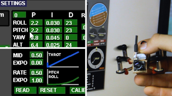
Before we go out and fly, while the drone is connected to our computer, let’s quickly go through some very basic PID tuning in MultiWii to smoothen out any potential pitch and roll oscillations.
We need to gradually lower the “Roll” and “Pitch” values on the P column of the P-I-D until those oscillations disappear. I got good results at 2.2 and even better stability at 1.6 on both the pitch and roll. However, this value may vary from drone to drone and it’s much better to play around with these values yourself to see what works best for your hardware.
Under the PIDs, we can reduce the drone's sensitivity and reactiveness to joystick inputs by lowering the RATE and raising the EXPO value to get a smoother-looking curve on the graph which results in a less reactive drone as it tends to be super sensitive by default.
Once again, we need to hit “WRITE” and then “READ” to save those changes.
16. FPV Headset
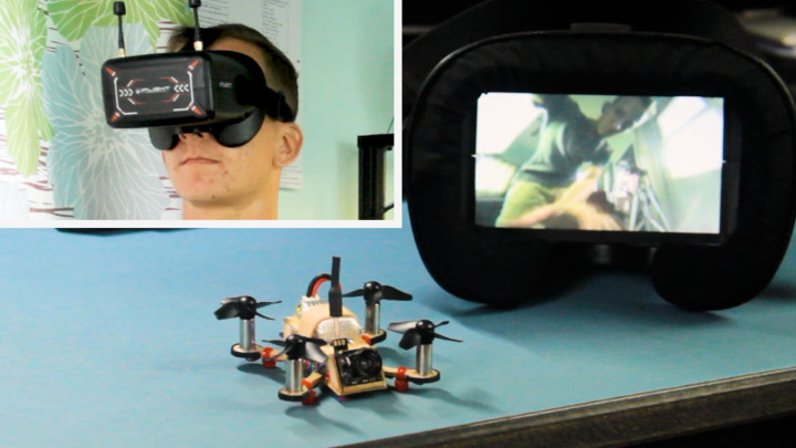
To view the FPV video feed, we’ll need a set of 5.8ghz FPV goggles/headset (see product link above), we should see the drone's FPV video feed displayed live when connected to the powered drone.
Pairing is as simple as turning on both the drone and goggles, matching the camera’s channel by pressing the “Auto Search” button on top of the headset to connect with the camera. When successfully paired up, we should see the drone’s live video feed displayed.
Recording video is possible on such a headset if it has a built-in DVR. Most of these cheaper FPV headsets contain a micro SD card slot at the top for storing recorded videos. We can make a recording by pressing the record button on top to start and stop while confirming the monitor’s recording status through looking at whether there’s a blinking red dot on screen.
17. Flying The Drone
To fly the drone, let’s first choose a suitable battery for it.
We can use any 20C or higher 150-250mAh LiPo cell (3.7V) that weighs no more than 7 grams and simply plugs into the connector on top, turning on the drone. To balance it, we can slide the battery either way depending on how it tends to veer off in flight. All up, the drone comes in at 30 grams. With a thrust to weight ratio of about 2 to 1, it is light enough to be considered a "light wind" flier according to the drone thrust scale chart - https://www.halfchrome.com/wp-content/uploads/2017/07/Thrust-Scale.png
To get set up with the drone, you simply power it on while lying on a flat surface, turn on the transmitter, followed by calibrating the drone's gyro with the following joystick movements - left stick pointed to bottom left corner and right joystick pointed down at the same time. After waiting for around 20 seconds for the gyro to fully calibrate - you can flip the arm switch to unlock the drone and the sky is yours!
If you’re inexperienced with flying drones, I’d suggest you watch some YouTube tutorials on learning the stick movements or try flying an existing non-FPV toy/brand drone that is more beginner-friendly for learning the controls.
18. Troubleshooting Tips and Key Takeaways
From my personal experience in making this little drone, I went through a heap of struggle and misunderstanding before I managed to get it flying. I faced issues such as the drone not having enough power to lift off, the Arduino kept resetting - preventing throttling up, and out-of-sync motors divided in diagonal pairs causing aggressive pitch/roll wobble.
Below, I list the things I tried that worked and didn’t work to counter the issues mentioned above as well as some tips and other measures you can take note on to get your own Arduino drone off the ground.
Troubleshooting that didn’t work:
1. Using weak motors (6g of thrust) of lower RPM that were all designed to spin only one way, not containing the counter direction pair - Preventing the drone from getting lift.
2. Adding filtering capacitors at motor leads and power inputs of Pro Mini, NRF24L01, and MPU6050 - Did not stop the drone from resetting.
3. Connecting motor driver signal wires to Arduino’s PWM pins through resistors - Did not stop the drone from resetting.
4. Changing the hardware and software PWM frequency from 500Hz to a higher value in the code in hope of running the motors smoothly to reduce electrical noise - Did not stop the drone from resetting.
5. Relying solely on perfectly stable landing gear to eliminate Pitch and Roll wobble - Did not stop the drone from wobbling off in the air.
Troubleshooting that worked:
1. Using 60,000 RPM coreless motors (14g or thrust) with Clockwise and Counter-clockwise rotating pairs - Gave sufficient thrust for liftoff
2. Placing a grounded copper/aluminum shield between sensitive electronics and motor driver - Stopped the drone from resetting and allowed for motors to spin up.
3. Lowering P column in the PID values for Pitch and Roll - Smoothened the out-of-sync diagonal motor sequence and allowed for steady flight.
Troubleshooting Tips:
- Use powerful coreless motors with higher RPM and bidirectional pairs
- Shield flight controller with copper/aluminum foil beneath or give sufficient spacing (spacing may only be practical with bigger drones)
- Raise or lower P column PID values for Pitch and Roll. If the drone wobbles fast, lower the value. If it wobbles slowly, raise the value. Keep adjusting incrementally until it’s flying stable.
- Add a 10 microfarad capacitor to power inputs of the NRF24L01 if there’s no radio connection.
- Do a diode test on transistors (MOSFETs) if one or more motors don’t seem to work properly. Replace a MOSFET if necessary.
Key Takeaways:
- Construct the drone's frame from popsicle sticks using provided blueprints or purchase a 3D-printed frame for added convenience. Following the frame blueprint, parts can even be cut out from flattened PVC pipe.
- Assemble a custom motor driver board with purchased or salvaged components to safely drive the coreless motors without damaging the microcontroller.
- Select and install coreless motors that provide sufficient thrust for stable flight, ensuring proper spinning direction and propeller orientation.
- Keep the drone’s weight to a minimum by selecting the smallest form factor of battery with 150-250mAh current capacity, sizing down or choosing modules that are as small as possible - every gram counts.
- Wire the drone's components meticulously, including the radio transceiver, flight controller, and FPV camera, to ensure seamless operation.
- Program the drone using MultiWii software, adjusting PID values for smooth flight and configuring transmitter controls for arming and mode switching.
- Troubleshoot common issues such as Arduino resetting, insufficient lift, and motor synchronization, employing strategies like shielding sensitive electronics and adjusting PID values.
Conclusion
Taking on the fun challenge of building a miniature DIY FPV drone controlled entirely by Arduino hardware has been an exhilarating and rewarding experience. From crafting the frame out of scrap parts such as popsicle sticks to meticulously wiring each component and fine-tuning the flight characteristics, this project has offered a wealth of learning opportunities and challenges for us makers
Through the integration of readily available Arduino-compatible modules and custom motor driver boards, we've created a compact and powerful mini quadcopter capable of delivering thrilling FPV racing experiences right in the comfort of our living rooms.
As we've navigated through the intricacies of DIY drone building, we've learned valuable lessons in electronics assembly, coding, and troubleshooting. From selecting the right components to tuning PID values and configuring transmitter controls, every step has contributed to our growth as makers.
While challenges such as Arduino resetting and motor synchronization may have tested our resolve, they've also provided valuable insights and opportunities for experimentation. Through perseverance and ingenuity, we've overcome these obstacles and emerged with a deeper understanding of drone technology and its applications.
In conclusion, building a miniature DIY FPV Drone controlled entirely by Arduino hardware is not just about creating a flying machine - it's for the experience-filled learning and the fun of being able to say you’ve built your own flying drone. As we take to the skies with our custom-built drone, we carry with us the knowledge and experience gained from this project, ready to tackle new challenges and push the boundaries of DIY!
To see the video tutorial and how the drone flies, watch my YouTube video embedded below.
Discussie (1 opmerking(en))