Multi channel isolated Smart Energy Meter for Distribution board

I want to monitor my energy consumption as detailed as possible. This means I would like to monitor each wire leaving the distribution board individually. Some time ago I read about the Maxim DS8102 / MAXQ3108 chipset and think this would be ideally suited.
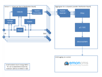
My idea is: One of the DS8102 per wire sample the data in a very small package. This will have only 4 pins (L in, L out and 2 N) and will use a shunt as current sensor. The data of this Dual Delta-Sigma Modulator and Encoder is manchester encoded. This makes it possible to transmit the data either using insulation capacitors or even more secure using a (mini-) toslink transmitter having optical insulation.
A central data aggregator (outside of the distribution board) then does the neccessary calculations. As it will have to handle many channels simultaneously and will have to do all the maths this might have to be a FPGA. This will then transmit the data to a microcontroller/soc/rpi which transmits the data to the open source energy monitoring server of the OpenEnergyMonitor project(http://openenergymonitor.org/emon/).
The problem is that I do not have enough experience for designing the sensor PCB. I would really appreciate help and/or ideas.
Discussie (5 opmerking(en))
petrus bitbyter 11 jaar geleden
Had a look at that DS8102 chip. There is a lot inside but what worries me is what's not in it. The chip should run at 3-3,5V and has a maximum voltage on all pins of 4V. Now the 230Vac mains is a rough and unforgiving environment with lots of nasty spikes, pulses and other disturbances So you will have to add quite some components to protect the chip. Not only for the power supply but also for the inputs. Protecting from overcurrent is another issue. If not done properly a downstream short will blow your circuit well before any fuse trips. The example in the datasheet cannot be considered a real design. Way too much details are missing.
Got an example of a microchip energy meter design. It has more details - the power supply for instance - but not enough to build reliable meter. Now there should be something left to do for a designer but I consider it to become too expensive both in time and money.
petrus bitbyter
Martin Kirsch 11 jaar geleden
Hi Markus,
I got nearly the same idea. I'm currently looking for a possibility to log all currents of each phase. The first idea was to create it by my own, but I think if you are finished you pay more money and time on this project than if you join a group of people following the same idea. I'm currently not shure to do it on my own or try to find some people doing the same. Yesterday I found an interesting project on the website openenergymonitor.com. They're doing nearly the same, but everything is already finnished. Okay the size coule be a little bit smaller, but you don't have the need for a sensor frontend and insulation. It seems that everything is open source, so you and me could contribute our own ideas.
If you wand to sense the currents and voltages I would prefer to use transformers instead of shunts and direct voltage contact. You can use a standard transformer 230VAC -> 9VAC to get the voltage curve and current sensors (coils) to get each current curve.
As analog preprocessor with some functions already included the device ADE7816 from analog devices could be a good starting?
What do you think about the different idea's?
Best regards
Martin
CBec 11 jaar geleden
Markus Reschka 11 jaar geleden
For the Sigma-Dleta Modulator you need a sinc3 Filter for getting the signal.
TI does have a very good Application note for that: http://www.ti.com/general/docs/litabsmultiplefilelist.tsp?literatureNumber=sbaa094 which even includes the VHDL Code for the sinc3 Filter.
Idea: Use the Elector FPGA Board, implement an manchester Decode, sync to the 0-1-0-1... Sync Information an feed the result to a sinc3 Filter.
Markus Reschka 11 jaar geleden
Let's start with my first ideas:
The sensor board should be very small. Just big enough for the following:
The wires used in a distribution boy are typcally massive wires. That means we can use Screwless connectors (2 Pins each). E.g. http://catalog.weidmueller.com/procat/Group.jsp?page=Group&groupId=%28%22group14881037827312%22%29
Mini-Toslink would be nice but so far I have not found mini toslink transmitters. Does anyone know such a transmitter?
What about power supply? Who knows how to build a good capacitor based power supply fulfilling the needs of the A/D converter DS8102 (http://www.maximintegrated.com/datasheet/index.mvp/id/6139) and s toslink transmitter (5 mA or less @ 5V).
Regards
Markus
Markus Reschka 11 jaar geleden
MarkDonners 11 jaar geleden
eduino.io #oetelx 11 jaar geleden
You are proposing reinventing the KWh meter based on a datasheet.
I have read the specs in the datasheet, it is one dual channel ADC and a dual core CPU that can communicate with it.
You propose a toslink for optical insulation.
I have to say, no do not try this please.
1) Hardware and software development is huge, expensive and complicated because of many reasons, including safety.
2) You can buy off the shelf pulse counters for a few euro's that are safe and do all the work for you already.
I propose you get an arduino to count the pulses and a wiznet board to make the results available in your browser or datalogger. Even that might be a big project for you depending on your experience.
Sample pulse counter : http://www.ebay.com.au/itm/ENERGY-POWER-45-AMP-LCD-DIGITAL-DISPLAY-KILOWATT-HOUR-METER-SINGLE-PHASE-KWH-/171050131701
Just my way of looking at it, if you like a major challenge to solve an already solved problem, go ahead.
Good luck,
Edwin van den Oetelaar
FPO 11 jaar geleden
Markus Reschka 11 jaar geleden