
Multi Light Timer 6BP 6Relay 6Duration
Lighting timer for 6 boxes or other. 6 low voltage push button inputs. 6 relay outputs, designed for lights with LED. Display on 2X16 LCD equiped with an I2C extension (PCF...) EEPROM function to store timer duration. The time delay can be adjusted separately whith two BP or double BP switch (mid-point rest) Duration of time delay from 1 min to 30 mins. Read-back of time delay durations in EEPROM memory Just modify in the code to extend maximum duration. We use millis() which leaves a margin.
A friend has built rental boxes (storage type).
Wanting to equip them with lighting, he thought of a stairwell type timer.He came over to my place, explained his needs to me and I answered him: "it exists all done!"
Tit for tact, he returns to me, ' "have you seen the prices !?"
Indeed, it's not given, well, nothing is free :)
I worked quickly on a sketch and established the price of a diy realization.
Knowing that the need was going to be double (6 boxes to come) I validated the specifications.
We will activate the input of an optocoupler, Cosmo 1010, using the Box push button.(Optional LEDs indicate support)
The BP information is retrieved on the output and the timing launch is processed through the ATmega328.
The output of the associated relay is activated during the time delay in memory.
NOTE:
-----------------------
The first prototype was not equipped with an optocoupler. Untimely tripping of lighting has been observed.
External pull-ups were installed on the assembly and the same malfunctions were observed.
Following the addition of the Cosmo1010 optocoupler, from the bottom of the drawer, no more untimely tripping was observed.
-----------------------
This code works with an Uno or a Nano but you must not use D13 WITH THIS CODE!!!
If Nano board, modify the #define BP6 definition (in A2 or A3) and wire accordingly;
#define BP6 (A2 or A3)
For the use of the Arduino shield relay card, the relay states must be reversed.
-----------------------
For the use or installation of an I2C LCD, to scan the I2C bus, see your favorite search engine.
This project uses the <LiquidCrystal_PCF8574.h> library
To program the Atmega328P CPU, I used the package (to be dragged into your additional board manager URL preferences)
https://mcudude.github.io/MiniCore/package_MCUdude_MiniCore_index.json
-----------------------
What the code does:
When objet starts,
we initialize the LCD and display a message, we install the Pins
we read the eeprom, if it is 0 found, we initialize and write the eeprom to the value of the minimum tempo time defined
The timeout values are displayed for approx xS, then we go to standby, the LCD backlight is off.
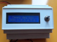
If action BP1 to BP6 a timer is launched, the display reactivates and indicates the box number(s) in service.
From standby or box in service:
Action SW0 we go to the setting menu
Action SW1 we will read and display the delay times.
Settings menu:
By action SW0, you enter adjustment mode, the LCD displays Box N°1 adjustment mode.
If action SW1, the time is incremented in steps of 1 min, from the minimum value to the maximum value TEMPO_MAX.
If action SW0, we validate the time and we switch to Box N°2 settings.
If the value must be modified, increment action, SW1, otherwise, SW0 to go directly to the next Box.
Arrived at the Box N°6 setting, we exit by action SW0, we write in EEPROM the time delay values of the
6 Box and a summary of all the timings is displayed on the LCD.
Depending on the state of the BOx timers, the LCD is turned off.
See assembly and user manual.
Use Code::TIMER_Use Code::TIMER_FOR_SIX_BOX_v2 located in author's update zip.FOR_SIX_BOX_v2 located in author's update
This code is free, do not hesitate to adapt it to your needs and to ask your questions.
FR:
Temporisateur d'éclairage pour 6 box
Multi Temporisateur d'éclairage
6 entrées Bouton Poussoir basse tension
6 sortie relais, prévu pour des éclairages équipés de leds.
Affichages sur LCD 2X16 équipé d'une extension I2C (PCF...)
Fonction EEPROM pour stocker les durées de temporisations.
Les temporisation sont ajustables séparément à l'aide de deux BP ou inter double BP (repos à point milieux) Durée de temporisation de 1mn à 30mns. Relecture des durée de temporisations en mémoire EEPROM
Il suffit de modifier dans le code pour allonger la durée maximum. On utilise millis() ce qui laisse de la marge.
//////////
Un ami a construit des box de location (type garde meuble) Voulant les équiper d'un éclairage, il a pensé temporisateur type cage d'escalier. Il est passé vers chez moi, m' exposé son besoin et je lui ai répondu : "ça existe tout fait ! "Du tac au tac, il me retourne, '"t'as vu les prix !?"
En effet, c'est pas donné, m'enfin, rien n'est gratuit :)
J'ai planché vite fait sur un croquis et établis le tarif d'une réalisation diy.
Sachant que le besoin allait être double (6 box à venir) j'ai validé le cahier des charges.
On va activer l'entrée d'un opto coupleur, Cosmo 1010, à l'aide du bouton poussoir de Box. (Des leds optionnelles indiquent l'appui)
On récupère sur la sortie l'information BP et on traite le lancement de temporisation au travers l'ATmega328.
La sortie du relais associé est activé durant le temps de temporisation en mémoire
NOTA :
-----------------------
Le premier prototype n'était pas muni d'opto coupleur. Des déclenchement intempestifs d' éclairages ont été constatés.
Des pull-up externes ont été installés sur le montage et les mêmes dysfonctionnements ont été constatés.
Suite à l'ajout d'opto coupleur Cosmo1010, issus de fond de tiroir, plus aucun déclenchement intempestif n'ont été constaté.
_________________
Ce code fonctionne avec un Uno ou un Nano mais il ne faut pas utiliser D13 AVEC CE CODE !!!
Si Nano board, modifier la définition #define BP6 (en A2 ou A3) et câbler en conséquences;
#define BP6 (A2 ou A3)
Pour l'utilisation de carte relais shield Arduino, les état de relais doivent être inversés.
-----------------------
Pour l'utilisation ou l'installation d'un LCD I2C, pour scanner le bus I2C, voir votre moteur de recherche préféré.
Ce projet utilise la librairie <LiquidCrystal_PCF8574.h>
Pour programmer l'UC Atmega328P, j'ai utilisé le package (à glisser dans vos préférences URL de gestionnaire de cartes supplémentaires)
https://mcudude.github.io/MiniCore/package_MCUdude_MiniCore_index.json
----------------------
Ce que fait le code :
Au démarrage,
on initialise le LCD et on affiche un message, on installe les Pins
on relis l'Eeprom, si c'est 0 trouvé, on initialise et écrit l'Eeprom à la valeur du temps de tempo mini défini
On affiche les valeurs de temporisation durant env xS, ensuite on passe en veille, le rétroéclairage du LCD est éteint.
Si action BP1 à BP6 une tempo est lancée, l'affichage se réactive et indique le ou les numéros de box en service.
A partir de veille ou box en service :
Action SW0 on va au menu réglage
Action SW1 on va lire et afficher les temps de temporisation.
Menu réglages :
Par action SW0, on entre en mode réglage, le LCD affiche mode réglage Box N°1.
Si action SW1 on incrémente le temps par pas de 1mn, de la valeur mini à valeur maxi TEMPO_MAX.
Si action SW0, on valide le temps et on bascule sur réglages Box N°2.
Si la valeur doit-être modifié, action incrément, SW1, sinon, SW0 pour passer directement au Box suivant.
Arrivé au réglage Box N°6, on sort par action SW0, on écrit en EEPROM les valeurs de temporisation des
6 Box et on affiche sur le LCD un résumé de l'ensemble des temporisations.
Suivant l'état des temporisation de Box, on éteint le LCD.
Utiliser le code :: TIMER_FOR_SIX_BOX_v2 situé dans le zip mise à jour de l'auteur.
Voir manuel d'assemblage et utilisateur.
Ce code est libre, n'hésitez pas à l'adapter à votre besoin et à poser vos questions.
Wanting to equip them with lighting, he thought of a stairwell type timer.He came over to my place, explained his needs to me and I answered him: "it exists all done!"
Tit for tact, he returns to me, ' "have you seen the prices !?"
Indeed, it's not given, well, nothing is free :)
I worked quickly on a sketch and established the price of a diy realization.
Knowing that the need was going to be double (6 boxes to come) I validated the specifications.
We will activate the input of an optocoupler, Cosmo 1010, using the Box push button.(Optional LEDs indicate support)
The BP information is retrieved on the output and the timing launch is processed through the ATmega328.
The output of the associated relay is activated during the time delay in memory.
NOTE:
-----------------------
The first prototype was not equipped with an optocoupler. Untimely tripping of lighting has been observed.
External pull-ups were installed on the assembly and the same malfunctions were observed.
Following the addition of the Cosmo1010 optocoupler, from the bottom of the drawer, no more untimely tripping was observed.
-----------------------
This code works with an Uno or a Nano but you must not use D13 WITH THIS CODE!!!
If Nano board, modify the #define BP6 definition (in A2 or A3) and wire accordingly;
#define BP6 (A2 or A3)
For the use of the Arduino shield relay card, the relay states must be reversed.
-----------------------
For the use or installation of an I2C LCD, to scan the I2C bus, see your favorite search engine.
This project uses the <LiquidCrystal_PCF8574.h> library
To program the Atmega328P CPU, I used the package (to be dragged into your additional board manager URL preferences)
https://mcudude.github.io/MiniCore/package_MCUdude_MiniCore_index.json
-----------------------
What the code does:
When objet starts,
we initialize the LCD and display a message, we install the Pins
we read the eeprom, if it is 0 found, we initialize and write the eeprom to the value of the minimum tempo time defined
The timeout values are displayed for approx xS, then we go to standby, the LCD backlight is off.
If action BP1 to BP6 a timer is launched, the display reactivates and indicates the box number(s) in service.
From standby or box in service:
Action SW0 we go to the setting menu
Action SW1 we will read and display the delay times.
Settings menu:
By action SW0, you enter adjustment mode, the LCD displays Box N°1 adjustment mode.
If action SW1, the time is incremented in steps of 1 min, from the minimum value to the maximum value TEMPO_MAX.
If action SW0, we validate the time and we switch to Box N°2 settings.
If the value must be modified, increment action, SW1, otherwise, SW0 to go directly to the next Box.
Arrived at the Box N°6 setting, we exit by action SW0, we write in EEPROM the time delay values of the
6 Box and a summary of all the timings is displayed on the LCD.
Depending on the state of the BOx timers, the LCD is turned off.
See assembly and user manual.
Use Code::TIMER_Use Code::TIMER_FOR_SIX_BOX_v2 located in author's update zip.FOR_SIX_BOX_v2 located in author's update
This code is free, do not hesitate to adapt it to your needs and to ask your questions.
FR:
Temporisateur d'éclairage pour 6 box
Multi Temporisateur d'éclairage
6 entrées Bouton Poussoir basse tension
6 sortie relais, prévu pour des éclairages équipés de leds.
Affichages sur LCD 2X16 équipé d'une extension I2C (PCF...)
Fonction EEPROM pour stocker les durées de temporisations.
Les temporisation sont ajustables séparément à l'aide de deux BP ou inter double BP (repos à point milieux) Durée de temporisation de 1mn à 30mns. Relecture des durée de temporisations en mémoire EEPROM
Il suffit de modifier dans le code pour allonger la durée maximum. On utilise millis() ce qui laisse de la marge.
//////////
Un ami a construit des box de location (type garde meuble) Voulant les équiper d'un éclairage, il a pensé temporisateur type cage d'escalier. Il est passé vers chez moi, m' exposé son besoin et je lui ai répondu : "ça existe tout fait ! "Du tac au tac, il me retourne, '"t'as vu les prix !?"
En effet, c'est pas donné, m'enfin, rien n'est gratuit :)
J'ai planché vite fait sur un croquis et établis le tarif d'une réalisation diy.
Sachant que le besoin allait être double (6 box à venir) j'ai validé le cahier des charges.
On va activer l'entrée d'un opto coupleur, Cosmo 1010, à l'aide du bouton poussoir de Box. (Des leds optionnelles indiquent l'appui)
On récupère sur la sortie l'information BP et on traite le lancement de temporisation au travers l'ATmega328.
La sortie du relais associé est activé durant le temps de temporisation en mémoire
NOTA :
-----------------------
Le premier prototype n'était pas muni d'opto coupleur. Des déclenchement intempestifs d' éclairages ont été constatés.
Des pull-up externes ont été installés sur le montage et les mêmes dysfonctionnements ont été constatés.
Suite à l'ajout d'opto coupleur Cosmo1010, issus de fond de tiroir, plus aucun déclenchement intempestif n'ont été constaté.
_________________
Ce code fonctionne avec un Uno ou un Nano mais il ne faut pas utiliser D13 AVEC CE CODE !!!
Si Nano board, modifier la définition #define BP6 (en A2 ou A3) et câbler en conséquences;
#define BP6 (A2 ou A3)
Pour l'utilisation de carte relais shield Arduino, les état de relais doivent être inversés.
-----------------------
Pour l'utilisation ou l'installation d'un LCD I2C, pour scanner le bus I2C, voir votre moteur de recherche préféré.
Ce projet utilise la librairie <LiquidCrystal_PCF8574.h>
Pour programmer l'UC Atmega328P, j'ai utilisé le package (à glisser dans vos préférences URL de gestionnaire de cartes supplémentaires)
https://mcudude.github.io/MiniCore/package_MCUdude_MiniCore_index.json
----------------------
Ce que fait le code :
Au démarrage,
on initialise le LCD et on affiche un message, on installe les Pins
on relis l'Eeprom, si c'est 0 trouvé, on initialise et écrit l'Eeprom à la valeur du temps de tempo mini défini
On affiche les valeurs de temporisation durant env xS, ensuite on passe en veille, le rétroéclairage du LCD est éteint.
Si action BP1 à BP6 une tempo est lancée, l'affichage se réactive et indique le ou les numéros de box en service.
A partir de veille ou box en service :
Action SW0 on va au menu réglage
Action SW1 on va lire et afficher les temps de temporisation.
Menu réglages :
Par action SW0, on entre en mode réglage, le LCD affiche mode réglage Box N°1.
Si action SW1 on incrémente le temps par pas de 1mn, de la valeur mini à valeur maxi TEMPO_MAX.
Si action SW0, on valide le temps et on bascule sur réglages Box N°2.
Si la valeur doit-être modifié, action incrément, SW1, sinon, SW0 pour passer directement au Box suivant.
Arrivé au réglage Box N°6, on sort par action SW0, on écrit en EEPROM les valeurs de temporisation des
6 Box et on affiche sur le LCD un résumé de l'ensemble des temporisations.
Suivant l'état des temporisation de Box, on éteint le LCD.
Utiliser le code :: TIMER_FOR_SIX_BOX_v2 situé dans le zip mise à jour de l'auteur.
Voir manuel d'assemblage et utilisateur.
Ce code est libre, n'hésitez pas à l'adapter à votre besoin et à poser vos questions.
Updates van de auteur