
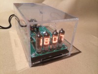
Numitron Arduino Clock and Thermometer [120740-I]
Published in the October 2013 Edition PLEASE NOTE:- In some editions fo the Magazine (GB, DE), the Temprature sensor is listed as a DS1820 - This should read DS18B20. The DS1820 is an old part and does not function correctly in this project.
Published in the October 2013 Edition
PLEASE NOTE:- In some editions fo the Magazine (GB, DE), the Temprature sensor is listed as a DS1820 - This should read DS18B20. The DS1820 is an old part and does not function correctly in this project.
The idea of this project is to look for the 'next step' for people who love to use the Arduino platform and to combine Arduino with Electronics.
In the best tradition of these sorts of projects I have decided to go for the classic clock and thermometer and to see if I can strech the Arduino UNO as far as possible.
For the Clock I decided against the traditional 7 segment LED's in favour of something much more beautiful in the form of Ex Russian Numitron bulbs.
So here we have the project, a Numitron bulb, Arduino UNO driven clock & thermometer built on a single board along the lines of traditional electronics builds, no shields, no modules and no plugins.
Courty
Update :7 Sep
Data sheet for the IV-9 Tubes, each filament is 19.5ma which is over 0.5A when everything is on, cant drive these from the Adruino directly so I am planning to use the 74LS47 BCD to 7 Seg TTL chip.
| Röhrendaten/ Tube Data | |||
| German | English | ||
| Typ | Type | IV-9 (ИВ-9) | |
| Hersteller | Brand | Reflector/ Sovtec | |
| Vergleichstypen | Substitudes | - | |
| Symbole | Displayed symbols | 7 Segment, PR | |
| Symbolhöhe | Symbol height | 10mm (0.400") | |
| Abmessungen | Overall dimensions | 11mm (0.433") dia. X 35mm (1.38") | |
| Pindurchmesser | Pin diameter | 0.5mm (0.020") | |
| typ. Betriebsspannung | typ. supply voltage | V | 4.5 |
| typ. Strom pro Segment | typ. current per segment | mA | 19.5 |
| Sockel | Base | TO-100, pin 1 zeigt nach vorne/ TO-100, pin 1 in front | |
| Fassung | Socket | Drahtanschluss, keine Fassung erf./ Wires, no socket needed | |
Update 10th Sep :
An interesting couple of hours playing with the IV-9 on a test board. a few lessons learned which will go forward into the final build.
1) you can't really multiplex the IV-9, being a tungsten filament bulb its just too slow and ether flickers or it to dim. each channel therefore will need its own driver and control lines. this mean the clock will be 4 digit as this is the limit of control lines I have on the ATMEGA328 chip.
2) The 74LS47 being a "high sink current" device appears to be more than happy driving the IV-9. I have added diodes for each line for a couple of reasons. the first was to help the multiplexing (no longer needed) and the second is to bring the drive voltage down from 5v to 4v to get into spec and to extend the tubes life. they will therefore be staying.
Onward and upwards as time permits
Update 17th Sep :
Having successfully completed the Breadboard tests and convinced myself the project is a 'goer' I decided to move on to a strip board full working model. this gives the opportunity to experiment with the clock and to test out a few other ideas. to keep with the Arduino theme I've chosen components and modules that are easily usable on the Arduino platform and ones that have good and well supported libraries..
For the realtime clock I'm using a 1307 and for the temperature sensing a 18b20, both are staples of the Arduino community.
The next picture is of the 4 x 74LS47's and the diodes going on - i've again gone for simple to understand and by using the 4 x 74LS47's without a latch or multiplexer it will use more pins but will be easier to understand when it comes to coding. each tube has its own BCD lines and each can be directly addressed by toggling the pins HIGH or LOW.
At this point I have also added the socket and supporting components for the Arduino processor
Update 18th Sep :
It works !, well the basic board with one tube works anyway.
to test if all was well I went through the normal checks without the processor and then added the pre-loaded ATMEGA328p with the Arduino UNO bootloader. this gave me the ability to use the Arduino programming console and to use the Seriel Monitor function if needed to debug. this is a very quick way to program and board and to see whats going on but it would be just as easy to add an ISP connector if needed.
To connect the board to the PC I have an eBay USB serial converter used mainly for programming Arduino Mini and Pro boards, these can be purchased for less than £10.00 and are an excellent investment..
Now were happy the logic works I added the rest of the tubes and connected them to IO pins, for the last few connections I used the 'Analog In' pins as they can be re-purposed as Digital Out pins from the software, Tubes 1, 2 & 3 have 4 BCD lines each and tube 4 have just 2 (we only need to show the numbers 1, 2 & 3 on that tube so only need binary digits 00, 01, 10 & 11) the decimal point is in tube 2 and is connected to its own I/O pin
Update 21 Feb 13 :
Firstly, thanks for the mention in the March Elektor magazine Clemens (I think :o) its really good to see Elektor.Labs really taking off. Having been in from the start I think it has massive potential.
Anyway, back to the project… I have indeed finished the project and its been running for 5 months as my bedside clock without a problem.
Further to the article above, I added a DS1307 real time clock chip as standalone the clock wouldn't keep good time, I now use the DS1307 as the source for time within the program.
One interesting find - Deep in the DS1307 datasheet is mention of processor clock noise on the power lines causing fast running, this is an issue I experience early on. Not a massive gain but it was in the order of a few seconds a day, just enough to be annoying. Other projects where I have used DS1307’s have keep time really well so I decoupled the power lines to the DS1307 with a 100pf cap and made sure the crystal was grounded and this seems to have cured the issue.
Just for Clemens, I have uploaded the schematic !
I will upload the code once I’ve cleaned it up, this was intended to be an experementers clock from the off and has proven interesting on the hardware and software front – as mentioned, I developed the software in the standard Arduino IDE and have managed to keep the code standard so anyone with some experience of Arduino will be able to follow the project and hopefully add their own touches and improvements.
If the concept of Arduino powered proper projects as a next step for Arduino fans (and AVR fans) is of interest, I have 5 or 6 other projects that follow the same format (Proper project but Arduino IDE programmed) and I’ll be happy to publish those too.
Please do leave comments and/or get in touch as it’s what make people come back and it’s what will power this community forward …
Update 1st May 13:
Work continues in getting the PCB designs ready (after a minor redesign on the PSU side) but for now i've uploaded a .hex file for the ATMEGA328P, this is enough to get the clock going using an AVR programmer.. i'll publish the Arduino .ino files as soon as the prototype is built and confirmed to be working.
Onward and upward..
Update 2nd Sep 13:
After many weeks work we are finally going to print in the next edition !
Apologies for the large gap in updates, we were working to get the article ready and testing everything before going off for summer. All back and refreshed now.
The good news is that the final design works well via the ISP header and via the Adruino serial interface so hackers of all abilities can get under the bonnet and play with the software. My two prototypes have been keeping good time for a few months now, one in my office and one next to the bed, they do give off a nice warm glow in the dark..
The PCB designs have been finalised, the code updated and the final versions of all the files will appear here soon, any questions/suggestions/hacks ether post them here or email me direct elektor@the-courts.co.uk
Paul
Update 20th Sep 13:
We're in the October Issue ! its cool to see the article in print in the UK edition but also in French, Dutch and Italian !
Hope you enjoy reading about the clock in the magazine.
Paul
Discussie (4 opmerking(en))