
One transistor power amp
An amplifier, as close as possible to an amplifying copper wire !
This is a single transistor (mosfet) power amplifier.
It produces about 5W RMS per channel.
No overall or local feedback. Only one MOSFET in the signal path!
It sounds amazing, produces no noise at all, and has an audio detail and a stereo image I have never heard before.
I think I will grow old with this amp :-)
Building suggestions:
- use metal film resistors only
- use oversized output capacitors: distortion happens only at the cut of frequency, so go as low as your ears and body can handle!
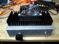
- use a large heatsink, this is a class A amplifier, and has an efficiency of about 25% (omg so bad, but hey I like the heat, esp. in winter times! )
- I use a 24V fan at low speed on my little heatsink, with extra filter to avoid motor hum. Use a bigger heatsink to avoid the fan setup.
- I use an old 24V laptop power supply, with extra filter to avoid switching noise. See scope images, it works pretty well !
- Clipping the amplifier brings a tube style distortion which is pleasant to the ear. (see scope image)
- Distortion firgures probably aren't that good but hey, it sounds just great the way it is !
(most of all) ENJOY!
It produces about 5W RMS per channel.
No overall or local feedback. Only one MOSFET in the signal path!
It sounds amazing, produces no noise at all, and has an audio detail and a stereo image I have never heard before.
I think I will grow old with this amp :-)
Building suggestions:
- use metal film resistors only
- use oversized output capacitors: distortion happens only at the cut of frequency, so go as low as your ears and body can handle!
- use a large heatsink, this is a class A amplifier, and has an efficiency of about 25% (omg so bad, but hey I like the heat, esp. in winter times! )
- I use a 24V fan at low speed on my little heatsink, with extra filter to avoid motor hum. Use a bigger heatsink to avoid the fan setup.
- I use an old 24V laptop power supply, with extra filter to avoid switching noise. See scope images, it works pretty well !
- Clipping the amplifier brings a tube style distortion which is pleasant to the ear. (see scope image)
- Distortion firgures probably aren't that good but hey, it sounds just great the way it is !
(most of all) ENJOY!
Want to build a project?
Bring your design to life with the Elektor PCB Service, powered by Eurocircuits. Upload the project files and order professionally manufactured PCBs or assembled boards through a proven European production platform.
Supporting KiCad, Eagle, Gerber, and ODB++ formats, the service is suitable for everything from prototypes and validation builds to series production and volume manufacturing.
Made in Europe. Fast. Reliable. Professional.
Discussie (2 opmerking(en))