
Platino Soldering Station [140107 ]

A simple Platino based soldering station for not too demanding (hobbyist) applications. Temperature range of 90 – 450 degrees Celsius with temperature readout on an LCD.
NEW Firmware ready
See also the SMD Soldering Station for Weller Soldering Tips [140010-I] for more discussions about this project.
Related Elektor Magazine articles
Platino Solder Station, issue 7, 2015
Platino - Versatile Board for AVR Microcontroller Circuits, issue 10, 2011
Platino, the return, issue 3, 2016
Introduction
A simple Platino based soldering station is designed for not too demanding (hobbyist) applications. This Platino based soldering device can be used to heat up the soldering bit to a temperature ranging from 90 – 450 degree Celsius and also to check the temperature of the soldering bit.
The project is about a cheap SMD solder station built as a Platino Add-on system. It supports active soldering tips from Weller (RT series) which contain the heating element as well as a sensor and a standard 3.5 mm jack. Together with the corresponding female connector you will get a compact SMD soldering iron with very fast heat up times of a few seconds. Also support similar soldering bit. The Add-on board consists of a low-noise amplifier for measuring the temperature via the ADC of the AVR, a power MOSFET stage to control the heating using PWM, LCD display and encoder for setting and displaying the temperature.
The elaborated design of the Elektor Platino board makes it easy to extend its capability, to develop devices of complex functionality with only a few additions.
New Firmware:
The current firmware lacks some features that are essential to prevent the tips from getting burned. Also the hardware needs a modification to have the detection working as desired. You need to add a 1Meg Ohm resistor between VCC ( 5V ) and the sensor input. This can be done at the IC2 by connection the resistor between pin 8 ( VCC ) and extend it with a wire to the sensor terminal. This is not a nice looking mod, but will be the only way to have good detection if the sensor fails.
The problem is, with bad contacts if the sensor disconnects you have a open input at the opamp and the values will be just random within a range of 50 to 460 degree. Also if the iron cant reach it's temperatur for a given time the sofware will trip a fault and shutdown.
A few new goddys also are now in the software, an automatic standy if the tip is not used. This means the station redices the temperatur to 100°C and a press on the rotary button brings it back to the desired value. Also there is a standby now if the station was 10 minutes in powersave the station will enter standby an cut power to the tip totally. A press on the rotary buttion will get the station alive. Also as the old software was written for the Atmel Studio 4, we decided to move it back to the Arduino framework, to give you the posibility to easily add new functions on your own. The surce of the new firmware is now on github and also you find prebuild hex-files as attachment.
About Platino:
First published in Elektor Magazine October 2011.
Platino 1.4 is published in Elektor Magazine March 2016
The name Platino is a playful reference to the French (and German) word ‘Platine’ meaning ‘circuit board’, with a slight wink at ‘Arduino’. It is a versatile circuit board for circuits based on an 8-bit AVR controller. With an ATmega168 or ATMega324 Platino can play the lead role in a large number of sketches. And for the most demanding builders it has a convincing trump in hand: it can be fitted with an ATmega1284!
Platino 1.4 is backwards compatible with Platino 1.3. Note that it has two extra jumpers for the LCD (JP15 & JP16) and that diode D1 was added to protect the FTDI cable. Mount D1 if the FTDI cable must be able to power the board (during MCU programming for instance).
Specifications:
- DC Input: 12V to 15V DC
- Elektor Platino with ATmega328P microcontroller.
- 16 X 2 LCD Display
- 3 way terminal block for connecting 3.5mm stereo jack socket for connecting weller RT series soldering bit.
- Heating temperature ranges from 90 – 450 degree Celsius.
Features:
- The heating is controlled by the PWM using Platino MCU
- Displays the current soldering bit temperature on LCD.
- Rotary encoder to vary the soldering bit temperature.
The Platino-based Soldering station is divided into two major sections one the hardware and another is software, both are responsible for the stability and accuracy of Input and output. The heart of the project is the PLATINO MCU board which contains MCU ATmega328P.
The Hardware consists of two sections
- Platino MCU board with LCD
- Soldering station Add-on Board.
Platino MCU board with LCD:
Platino Series is easy to use for developing AVR MCU based applications just by adding simple add-on board of supporting functions at input stage. This board supports the LCD depending upon the requirements and also the AVR MCU depending upon functions to be performed by the circuit. Here platino consist of ATMega328P MCU and 16X2 LCD with backlight. The board reads the temperature of the sensor signal through the MCU board on pin PC0 of MCU and displays the soldering bit temperature on LCD. Also the PWM generated by the MCU on pin PB2 is used in controlling soldering bit temperature. The PWM is generated on the basis of the temperature set to heat the soldering bit. To set the required temperature the platino board consists of a rotary encoder for easily varying the required temperature. The set temperature is also displayed on LCD. This board powered from add-on board at 5V supply voltage.
Soldering station Add-on Board
The Add-on board consists of a low-noise amplifier using IC2a OPA2336 for measuring the temperature. The heater and sensor output from the weller soldering bit is connected to 3.5mm stereo socket to add-on board through connector K1. The sensor signal connected to IC2a non inverting pin 3 through resistor R1 and output of IC2 at pin 1 connected to PC0 pin of platino MCU for reading temperature of soldering bit.
Transistor T1 is used to control the temperature of the soldering bit whose gate is control by transistor T2. PWM signal from pin PB2 of platino MCU is connected to gate of transistor T2 via resistor R6.The circuit can be operated from 12 V to 15V DC supply with 2.5 to 3A current rating.
The power can be connected to connector K6 on add-on board. This board also contain 5V regulator for generating 5V for add-on board as well as platino board. IC1 MC7805 is used for generating 5V supply. The board also consists of a MOSFET for controlling the soldering bit temperature.
Software:
The software for the project is written in AVR Studio for ATMEGA328P microcontroller. The Platino board is used for further development of the project.
The software reads the temperature of the soldering bit via MCU ADC pin PC0 and displays the current temperature of the soldering bit on the LCD and allows the user to set the temperature of soldering bit using the rotary encoder.
The heating of the soldering tip directly takes place from the MOSFET from the actual temperature to 5 degree Celsius less than set temperature. Above 5 degree from set value to the set value the soldering bit is heating using the PWM from MCUvia PB2 pin. If the actual temperature goes above the set temperature value then the MOSFET is switched OFF.
The ADC of the MCU periodically reads the temperature of the soldering bit and adjusts the temperature as per the set temperature value using PWM
Building the Prototype:
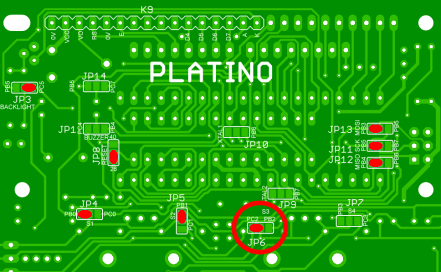
First ‘Jumper’ the platino board as shown in Table 2. The other components should solder after placing the required jumpers.
Note: this project uses Platino v1.3, for Platino v1.4 and higher place JP15 & JP16 in postion 'D'. Also you may need to mount diode D1 if the board must be powered by the FTDI cable (during MCU programming for instance).
Now build the Platino with its LCD, rotary encoder, ATmega328P MCU and all other components. Refer to the Platino component list below to find out which parts must be mounted. Please take care that you mount the MCU on the same side as the LCD and the rotary encoder.
The add-on board that consists of the main circuitry for the soldering station that is connected to the Platino board via connectors K2 and K3. The Add-on board of soldering station is so designed to fix exactly to the back of Platino board with the help of connectors.
Testing:
- Connect the 3.5mm stereo socket to connector K5 and plug the TR1 soldering bit in it.
- The device is powered up through connector K6 with 12V DC adapter.
- Set the temperature for heating the soldering bit using the rotary encoder.
- The LCD will show the actual temperature of the soldering bit.
- As the temperature of the soldering bit reaches the set value you can use the soldering bit to solder SMD component on PCB.
| Pin designation | Function |
|---|---|
| PB0, PB1 | Rotary encoder |
| PC2 | Rotary encoder push button |
| PB2 | PWM output |
| PC5 | LCD backlight control |
| PC0 | Temperature sensor ADC input |
| Jumper | Position |
|---|---|
| JP3 | PC5 |
| JP4 | PB0 |
| JP5 | PB1 |
| JP6 | PC2 |
| JP8 | '28' |
| JP11 | PB5 |
| JP12 | PB4 |
| JP13 | PB3 |
| Platino v1.4 & higher | |
| JP15 | D |
| JP16 | D |
Component List Platino
Resistors, all 5%, 0.25W
R3 = 47Ω
R4, R5, R6, R7, R10, R12 = 10kΩ
R11 = 4.7kΩ
P1 = 10kΩ trimpot, horizontal
Capacitors
C5, C6 = 100nF, 0.2” pitch
Inductor
L1 = 10µH
Semiconductors
IC1 = ATmega328P-PU, programmed (Elektor Store # 140107-41)
T1 = BC547C (Platino 1.3) or 2N3904 (Platino 1.4, or BC547 mounted on LCD side)
D1 = 1N5817 (Platino 1.4 only)
Miscellaneous
S5A = rotary encoder with integrated pushbutton (Alps EC12E2424407 or equivalent)
K2, K6 = 6-pin pinheader, 0.1” pitch, straight
K3 = 6-way (2x3) pinheader socket, 0.1” pitch, straight
K5 = 8-way pinheader socket, 0.1” pitch, straight
K9 = 16-way pinheader socket, 0.1” pitch, straight
LCD1 = LCD, alphanumeric, 2x16 (Elektor Store # 120061-74)
DIP28-narrow IC socket
Discussie (18 opmerking(en))