Poor man's ChipWhisperer - or a SmartCard Tweaker
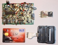
This is a simple and cheap device for all kinds of non-invasive attacks on protected MCUs and SmartCards (including credit cards!). Won't outperform a 3000$ variant of fully digital FPGA-based ChipWhisperer, but will work better as a learning/training platform for non-invasive tweaking attacks, thanks to fully accessible and observable signal paths.
I got inspired for this project after I saw this ruthless destruction of a credit card :) https://www.elektormagazine.com/news/what-is-inside-my-credit-card .
Protected secrets like credit card PINs, or protected MCU firmware can be extracted using different non-invasive attacks (attacks performed without decapsulating the silicon die). These attacks are usually based of various fault-injections - or inputting badly formatted input data, or sending signals of incorrect amplitude and frequency. Lowering supply voltage or abruptly cutting the power will also make the DUT (device under test- or actually attack) perform some uncontrolled action and hopefully reveal its secrets.
Using a combination of analogue and digital circuits, all controlled by a simple Atmega8, this device can succeed in defeating many protected DUTs, and still work as a good learning/training platform, better than a fully digital FPGA-based ChipWhisperer:
https://www.newae.com/chipwhisperer .
Besides this, you will need an average digital oscilloscope/logic probe, an analogue oscilloscope with a 100-200MHz bandwidth, and PC running software like Matlab and/or LabView for acquisition and processing of captured signals.
Discussie (13 opmerking(en))
Wavelight 1 jaar geleden
lux36 1 jaar geleden
Basically a medium-speed volt glitch during erase procedure.
Start at some normal voltage, decrease below 1.0 V during memory erase phase, then increase during lockbit removal.
Microsecond timing, not nanosecond.
Haven't tried it yet, this is just an approximate description.
Wavelight 1 jaar geleden
lux36 1 jaar geleden
J.F. Simon, Elektor 1 jaar geleden
lux36 1 jaar geleden
Milan Markovic 1 jaar geleden
Are you still in Zagreb?
I would try to send you a PIC16F1829 mcu lock flash for testing.
Where are you from, can I get your contact ?
It's my E-mail : milanmarkovic194@gmail.com
Wavelight 1 jaar geleden
lux36 1 jaar geleden
Why do you prefer a single-side PCB? Isn't it easier to use the design files already published along with the article?
Wavelight 1 jaar geleden
lux36 1 jaar geleden
LMV761 is a fast push-pull output comparator (can turn the DUT off in a few nanoseconds), easily available on Ebay:
https://www.ebay.com/sch/i.html?_from=R40&_nkw=lmv761&_sacat=0&_sop=15
ab cd 2 jaar geleden
I've been experimenting with modern smartcards (4G / USIM) with very limited success (due to lack of information about protections, I think), have you played with that before?
lux36 2 jaar geleden
Milan Markovic 2 jaar geleden
lux36 2 jaar geleden
Milan Markovic 1 jaar geleden
I tried and succeeded with Glich in the power supply to get the hex part.
Valeriy Polyakh 2 jaar geleden
Thanks for this fascinating development. I think many people would appreciate a PCB design, so that a PCB could be ordered from somewhere. You could even make some money on it.
I'd really like to make this device, but doing it entirely on a prototyping board feels like too much work and potentially too much debugging until the device works.
lux36 2 jaar geleden
Content Director, Elektor 2 jaar geleden
ElektorLabs 2 jaar geleden
The PCB design files etc. as a KiCad6 project have been added to the project. The zip also includes gerber & PDF files. The BoM was added as a separate file. Enjoy.
Please note that this project will appear in the January/February 2023 printed edition of Elektor Magazine, so stay tuned.
Wim Ton 3 jaar geleden
I am aware of Mr. Skorobogatov's work. You may have noticed that glitching attacks on debug interfaces are a kind of black hole on the search engines. Allegedly, because the chip manufacturer's lawyers hit you like a ton of bricks if you dare to publish something.
The modern bank cards are quite secure. After all, the attacker has an attractive business model: spend someone else's money and get away with it.
Bank cards might be defeated if the attacker spends months or years. But that is not considered a useful business model. See the work of: https://en.wikipedia.org/wiki/Christopher_Tarnovsky.
A step further to architecture: design your system that the damage is limited, even if the attacker has all the design documents and the keys of a few devices. Worth reading are the JIL (Common Criteria Joint Interpretation Library) documents on "attack potential". Unfortunately, this is difficult to explain to upset customers.
Designing secure protocols is notoriously difficult: see the work of Burrows, Abadi, and Needham. A.k.a. BAN logic.
lux36 3 jaar geleden
Anyway, when the ClearNet fails, there is always the Dark One :)
Wim Ton 3 jaar geleden
Modern bankcards must pass a rigorous security test before being deployed. They must be able to withstand an invasive white box test for several weeks. White box: the attacker has the full design documentation. Invasive: except for glitching, the attacker can also fire electrons or photons on selected areas of the bare chip.
You will have more chance by exploiting specification flaws such as: https://cardis2021.its.uni-luebeck.de/papers/CARDIS2021_Dubreuil.pdf or https://www.cl.cam.ac.uk/~rja14/Papers/API-Attacks.pdf
Wim Ton
lux36 3 jaar geleden
https://www.cl.cam.ac.uk/~sps32/mcu_lock.html
to repeat his experiments. I haven't seen his schematics. His webpage is from 2001, last updated in 2011.
Your expert advices are always appreciated, the same as your sense of humor :)
I have some questions for you now:
1.) Are you familiar with dr. Skorobogatov's work?
2.) Speaking about the modern bankcards (made after 2020), I suppose they are practically impossible to defeat non-invasively, except in case of serious design flaws. Is this correct?
lelion95 3 jaar geleden
lux36 3 jaar geleden
lelion95 3 jaar geleden
Lionel
lux36 3 jaar geleden
Are you familiar with dr. Skorobogatov's work?
lelion95 3 jaar geleden
Are you familiar with Komerling ? (the well known pay-tv smartcard hacker)
I have stoped the smart cards tamper fault analysis middle 2005.
if i remenber correctly, I believe dr Skorobogatov's begin his activitys near the same period...
lux36 3 jaar geleden
https://www.cl.cam.ac.uk/~sps32/mcu_lock.html
I also know about Chris Tarnovsky, but not in much details. Do you have any links to Komerling's papers? I would like to learn about his work as well...
lux36 3 jaar geleden
It works like this. When the Funcard MCU (Atmel AVR AT90S8515) is protected, both memory lockbits are programmed to 0. The flash memory then can't be read, only erased. In serial programming mode (/RESET input pulled down to 0V), the "Chip Erase" command will first erase the flash memory (revert all the flash bytes to 0xFF) and then erase the lockbits (deactivate them by reverting them to 1).
The design flaw present on many Atmel AVRs (not all) enables to crack the protection in the following way. If the power supply voltage is lowered below the rated minimum (2.7V), down to 1.6-1,7V, there won't be enough power to erase the flash memory, but erasing the lockbits will still be possible. The procedure is started at 1.1V and the voltage is gradually increased. The lockbits were successfully removed at 1.62V, and the flash memory wasn't erased!
On the terminal screenshot you can see that if you try to read firmware or signature from a protected Atmel AVR, you will get 0x00, 0x01, 0x02, 0x03 response, and thus you know that it is protected. Once you get the correct signature (0x1E, 0x93, 0x01 for AT90S8515) , you are ready to read the firmware - the protective memory lockbits are removed.
lux36 3 jaar geleden
The LMV761 comparator is used here to quickly cut the power to the Smartcard (in a matter of 10ns) if the current through R20 rises above a certain threshold (Vt, defined with OC1A PWM). If the Funcard tries to write to EEPROM, the current will rise, so writing to increase the PIN counter will fail if quickly switched off.
This way, the ATM8 will just have to try all the 10.000 possible PINs. It takes several ms to complete the EEPROM write cycle, so cutting the power after 10ns is fast enough.
In this demo, the correct PIN was 0295. I did more than 100.000 brute- force attempts, both on internal EEPROM and AT24C, there was no damage to EEPROM memory cells.
The oscilloscope (Tek-466 100MHz analogue storage scope) screenshot was captured in fast-storage mode, at 1V/div and 10ns/div (The fastest the Tek-466 can do is 5ns/div). The rising pulse is the LMV761 output on CH1 and the falling pulse is the Vcc2 on CH2 when cutting the power supply. The delay is less than 10ns, which is fast enough to abort writing to EEPROM.
This simple attack works well on old Smartcards which write to EEPROM only on wrong PIN attempts, and which have no defenses like random current noise to mask the internal operations.
New credit cards first increase the counter, write it in EEPROM, then check the PIN, then reset the counter to zero if the PIN was correct, all of this while adding random noise to power supply current. They can be attacked by recording current on R20, making several thousand recordings, filtering the noises and then carefully analyzing the data.
brute-force-pin-completed.jpg (180kb)
brute-force-pin-oscilloscope-10ns-div.jpg (675kb)
lux36 3 jaar geleden
Adjust the shape of the glitch using P4, P5, and P6. Use P3, S3 and S4 to adjust delay and sync. On the terminal screenshots, the results are read the same as in the previous example. The power supply voltage for the Funcard was set to 2,24V. The volt glitch was about 1.5V deep. The oscilloscope was set to 50ns/div and 1V/div, like in the previous example.
Using this Chipwhisperer, you can actually perform volt-glitches in three ways:
1.) Slowly change the Smartcard power supply voltage using PWM on OC1B. Takes at least 10ms to stabilize.
2.) Fast glitching with 50-100ns pulses generated through C19, P4-P6, P7, T5, T7, T8, T9. Set the JP12 or JP13 to choose undervolt or overvolt variant. Increase the C19 if longer glitches are needed. Be careful if using JP16, too high overvolt glitch may incinerate your Smartcard.
3.) Medium speed glitching using P8, P9 and PC5 output. If PC5 is set as input, the (mid-level) voltage is defined with OC1B PWM. Quickly pulling the PC5 up or down (as MCU output) will quickly decrease/increase the Vcc1 to levels defined with P8 and P9. It takes 10-20us to complete these shifts.
The Vcc2 is limited to cca. 6.0V with red LED4 (2.0V+5.0V=7V, minus 0.7V (UbeT1), minus 0.3V (UcesT7)), but fast overvolt glitch can still increase it to 9V through T8. Adjust it on a dummy load first. Almost every 5V MCU or Smartcard still works OK at 6V (which is kept as a slow overvolt glitch option).
volt-glitch-oscilloscope.jpg (794kb)
no-glitch-demo-20220330202235.jpg (191kb)
volt-glitch-demo.jpg (191kb)
lux36 3 jaar geleden
Set the P1 and P2 potmeters to get the glitch like shown on the pictures. The oscilloscope was set to 50ns/div and 1V/div.
Terminal window:
-Column 1 -the 16bit result of math operation - wrong when the glitch was successful
-Column 2 - a delay until firing a glitch- glitching in a different moment in time gives different results
-Column 3 - a checksum (a sum of two bytes if the 16-bit result) calculated by the Funcard)
-Column 4 - a checksum (a sum of two bytes if the 16-bit result) calculated by the ATM8 MCU)
-Column 5 - "Error!" if columns 3 and 4 don't match
clk-clitch-oscilloscope.jpg (791kb)
no-glitch-demo.jpg (204kb)
clock-glitch-demo.jpg (204kb)