
Elektor Quasi-Analog Clockwork kit - An Elektor Classic - A remake

A digital clock with an analog appearance. 144 3 mm LEDs in a circle show 12 hours with a 5 minutes resolution. 11 standard logic IC’s are used. All parts are through hole. Power supply can be any 5VDC low power AC adapter.
Original design by P. Hogenkamp (Elektor January 1995)
This project is an Elektor Classic. A kit with all parts, PCB and a wooden stand will be available at Elektor.
Digital watches with displays consisting of numbers only have lost much of their popularity over the last few years. They are now outnumbered by traditional dials with hour and minute hands actuated by a digitally controlled stepper motor. These watches (and clocks) are the best of both worlds because they have an analogue readout with digital control. The LED clock described in this article is based on the same principle, only there are no moving parts at all.
Notes on the 2024 Remake
A number of changes were made by Elektor Labs to make this 30-year old design compatible with components, insights and technologies available almost 30 years after its original publication.
Circuit Description
The quasi-analogue clockwork uses 144 LEDs (light emitting diodes) to indicate the time on a round, quasi-analogue dial with a diameter of about 143 mm. One of twelve green LEDs lights at maximum intensity to mark the hours, while the other eleven are dimmed. Between two green LEDs sit 11 red LEDs, each of which represents a period of five minutes. In this way, the time is indicated with an accuracy of five minutes. This would seem to be enough in view of the mostly decorative function of the present clockwork.

Fig. 1. Schematic of the Quasi-Analog Clockwork
The complete circuit diagram of the clockwork is given in Figure 1. The oscillator section of counter/divider lC1 is configured as a quartz oscillator with a 32.768 kHz crystal. The high value of R21, (330 kΩ, ensures the total power delivered to the crystal is well below the maximum drive level of 1 µW (more would reduce its lifespan). The total divider for the 5-minute pulse is created in two parts. The CT11 output of counter/divider IC1 (a CD4060) ticks at 8 Hz and clocks the second counter divider, IC11 (a 74HC4040). IC11 must divide 8 Hz by 2400 to create a 1/300 Hz pulse rate, i.e., a 5-minute pulse. A total divisor of 9,830,400 is achieved by detecting the binary code ‘2400’ with the aid of IC2A. In numbers: 2400 = 211 + 28 +26 + 25. When the value 2400 is reached, a CLK pulse is generated via R5, C1, IC3C, and IC3D, resetting IC11 (CT=0). The CLK pulse also increments the count of IC5 by 1. The other input of IC3D is connected to pushbutton S1 and serves to adjust the clock. The pulse supplied by the pushbutton is debounced by network R3-R2-C3 and IC3D. Every time the button is pressed, the readout advances by one LED position.
Counter/divider IC5 (74HC4024) operates as a 5-minutes counter and has 12 states, corresponding to 0, 5, 10, 15, 20, 25. 30, 35. 40. 45, 50 and 55 minutes. The outputs of IC5 determine which channel of multiplexers IC7 and IC9 (both 74HC4051) is actuated. The multiplexers’ Common pins are connected. For example, when all multiplexer Select inputs and the active-low Enable (pins 11, 10, 9 and 6) are held at 0, the anode terminals of the LEDs connected to output A0 (D1, D13, D25, D37, D49, D61, D73, D85, D97, D109, D121 and D133) are connected to the +5 V supply rail via a 2.2 kΩ resistor, R1. IC4A inverts the fourth bit of counter IC5 to enable IC9 when IC7 is disabled and vice versa. To make an LED light, however, its cathode must be pulled to Ground and that is done by multiplexers IC8 and IC10 (both 74HC4051), which have their Common pins joined and tied to ground via R4 (1 kΩ). The binary pattern out of counter/divider IC6 (74HC4024) is applied to the Select and Enable inputs (IC10 through IC4B, same function as IC4A) and determines which LEDs have their cathodes connected to Ground through the MX0 through MX11 signal lines. As soon as IC5 reaches state ‘12’ (corresponding to 0 minutes), the counter is reset via IC4C and IC4D. Also, IC6 receives a clock pulse which marks the start of a new hour. Incrementing the count in IC6 results in the next output of IC8 or IC10 becoming active. The multiplexers ensure that the cathodes of the selected LEDs are connected to R4. As soon as IC6 supplies the binary code ‘12’, a reset pulse is generated via IC3B, R7, C4 and IC3A. This pulse resets IC6 to state ‘0’ enabling the counter to start counting another 12 hours.
As already mentioned, the display has 132 red and 12 green LEDs. The green LEDs light continuously at low intensity due to their cathodes connected to Ground via 8.2 kΩ resistors (R8-R19). Since the anodes of the green LEDs are connected to R23, a constant current of about 0.2 mA flows through each LED. At the full hour, the relevant green LED must light at maximum intensity. That is achieved by connecting-in R4 (via MX0 through MX11) through a diode (D145 through D156). This trick explains why the LEDs connected to line A0 are wired differently in the matrix. The current is also increased by connecting R25 in parallel with R4 via T2. R26 is connected to virtually +5 V through IC7 and R1. Due to buffer T1, the voltage drop across R1 is then only 0.1 V.
LED D162 lights as a soon as the supply voltage is present. The last LED on the dial, D163, is located in the center of the dial and flashes slowly at 0.5 Hz to indicate that the clock is ‘ticking’. 5 volts DC from a DC adapter is connected to screw-terminal block K1 and that provides the clock’s supply voltage. D164, a 1N4004, protects against wrong polarity. The current demand from the clock varies from 6 to 11 mA, so the 5 V DC adapter can be a low-power type.
Construction
The PCB is routed doubled-sided and wire bridges aren’t necessary. Mount the LEDs close to the board surface to keep the clockwork as flat as possible. Also use miniature ceramic decoupling capacitors. If you are confident about your soldering skills, you may fit the ICs without sockets. In that case take precautions against static charges when soldering the ICs.
The clock should start to work the moment 5 VDC is applied to K1 (read 32.768 kHz reference clock). Which LED will light first is random and depends on the state of counters IC5 and IC6 at power-up. The LED at the top is green LED D1, indicating 12:00. Every time S1 is pressed, the clock is advanced five minutes.
The finishing touches to the clock depend on your own creativity. For instance, the dial may be covered by a bezel, which partly obscures the components but leaves the active LEDs clearly visible. Alternatively, a piece of transparent acrylic panel leaves ‘the works’ in sight. And that, arguably, will be the best option for the true electronics enthusiast.
32.768 kHz reference clock
While testing the standard quartz oscillator with a 74HC4060 and a 32.768 kHz crystal, the oscillator worked but produced a wrong and too high random frequency. Adding a small low pass filter (330 Ω/100 pF) seemed to work. But, to be sure a test was done with 9 different crystals from 8 manufactures. 1 of the 9 crystals didn’t work with the extra filter. Testing the same oscillator circuit with a standard 4060, from the 4000-logic series, the oscillator worked correctly with all crystals. The HC-logic version apparently causes enough interference in the circuit of the oscillator, due to its the very high impedance, most likely caused by the higher switching speed, even on a PCB with a ground plane. And even when the frequency was almost correct it was not as stable as is to be expected from a quartz oscillator. Fortunately the CD4060 is still widely available and still manufactured.
A small trimmer (C7) was added to adjust the frequency to exactly 32768.000 Hz, so the clock will show the correct time for a long while, despite the 5 minute resolution of course. The frequency of pin 1 of IC1 is 8 Hz, the oscillator frequency divided by 2^12. A probe can easily be connected to this pin to measure it with a frequency counter.
But, a bug reported by many is a quartz oscillator with a 32.768 kHz crystal and a 4060 not starting at power-up. I noticed this also and touching the crystal is enough to make the oscillator start. Changing values didn’t help, also replacing the crystal with different types didn’t solve it. Even stranger, adjusting the frequency to a perfect 8 MHz makes it most likely a permanent issue. Observe if LED D163 is blinking at power-up. Tuning the oscillator to a slightly deviating frequency can make the oscillator start at power-up (but sometimes not). It’s up to you if this is acceptable. Otherwise simply touch the crystal and the oscillator will start. After a power outage you will need to set the clock again anyway and then also watch if LED D163 is blinking. Another way is to place the crystal fully upright, this seems to solve it. So somehow the parasitic capacitance between the crystal and the ground plane is the culprit (?).
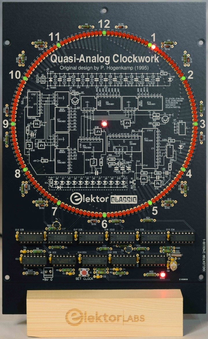
Fig. 2. The PCB placed in a wooden stand and powered.

Fig. 3. Side view of the clock in the wooden stand.
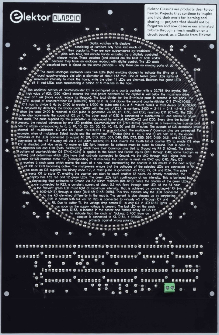
Fig. 4. View on the back of PCB 240118-1 v1.1. All parts are fitted
PCB
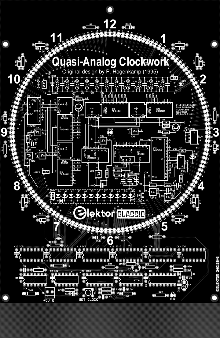
Fig. 5. Top overlay of PCB 240118-1 v1.1 of the Quasi-Analog Clockwork.

Fig. 6. Bottom overlay of PCB 240118-1 v1.1 of the Quasi-Analog Clockwork.
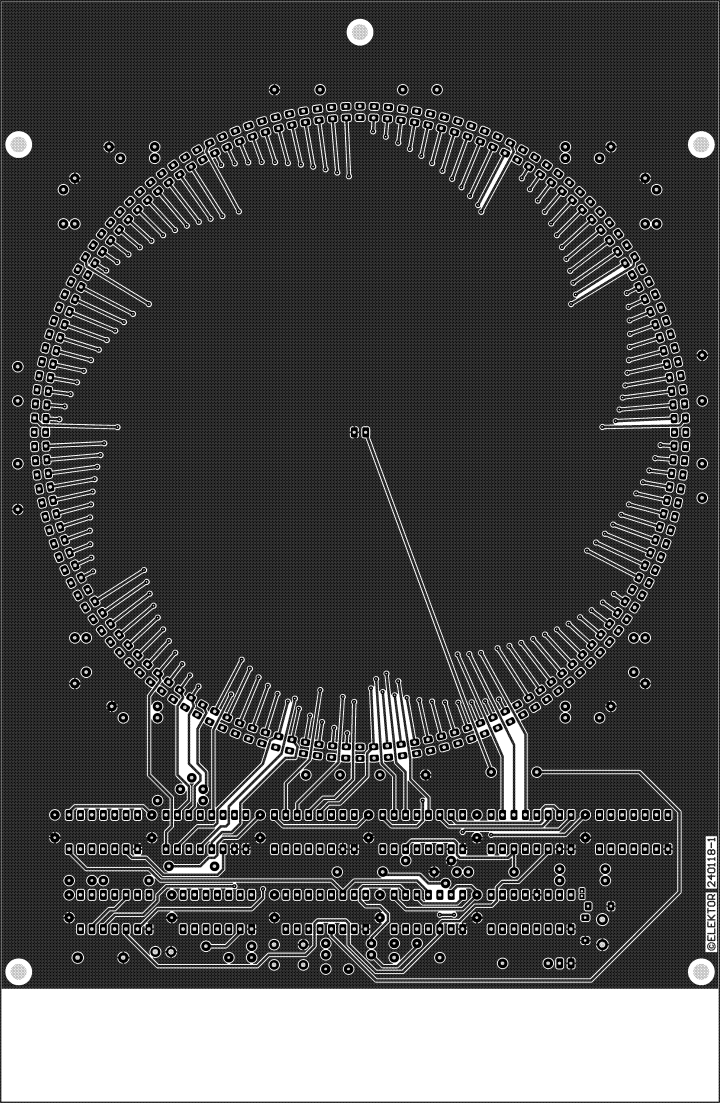
Fig. 7. Copper top of PCB 240118-1 v1.1 of the Quasi-Analog Clockwork.
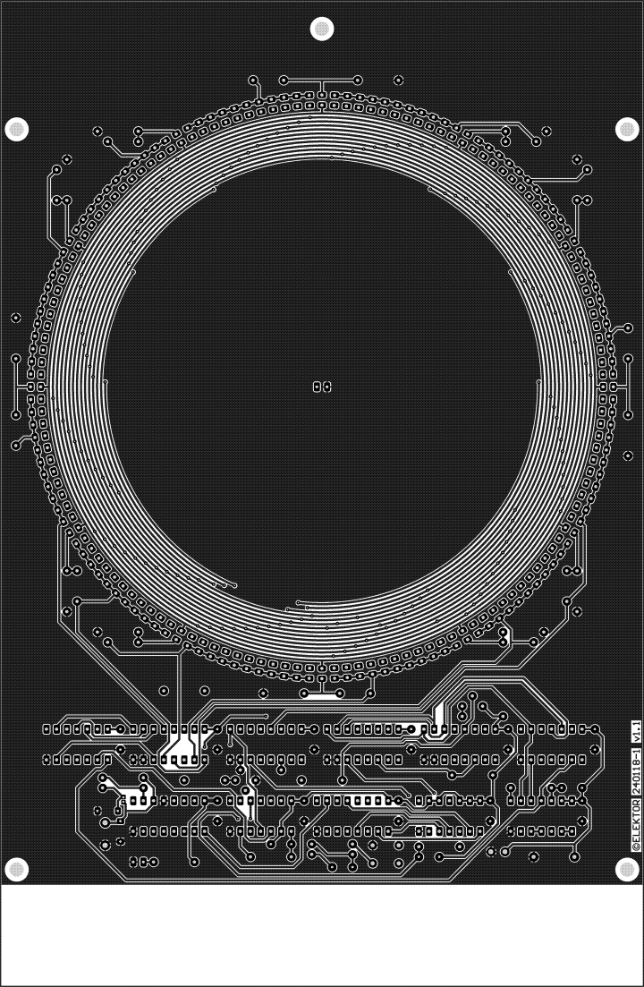
Fig. 8. Copper bottom of PCB 240118-1 v1.1 of the Quasi-Analog Clockwork.
Component List
Resistors
(body 2.5 × 6.8 mm)
R1, R22, R24 = 2.2 kΩ
R2 = 390 kΩ
R3, R5, R6, R7 = 82 kΩ
R4 = 1 kΩ
R8-R19 = 8.2 kΩ
R20 = 20 MΩ
R21 = 330 kΩ
R23 = 560 Ω
R25 = 470 Ω
R26 = 100 kΩ
Capacitors
C1-C4, C8-C18 = 100 nF, 50 V, ceramic X7R, lead spacing 5 mm
C5 =22 pF, 50 V, ceramic C0G/NP0, lead spacing 5 mm
C6 = 10 pF, 50 V, ceramic C0G/NP0, lead spacing 5 mm
C7 = 3-10 pF trimmer, BFC280823109 Vishay/BCcomponents
Semiconductors
D1,D13,D25,D37,D49,D61,D73,D85,D97,D109,D121,D133 = LED, green, 3mm
D2-D12,D14-D24,D26-D36,D38-D48,D50-D60,D62-D72,D74-D84,D86-D96,D98-D108,D110-D120,D122-D132,D134-D144,D162,D163 = LED, red, 3mm
Important: 3 mm round LED’s D1-D144 must have a flat side, no ledge!
D145-D156 = 1N4148, DO-35
D164 = 1N4004, DO-41
T1, T2 = BC547B
IC1 = CD4060, DIP-16
IC2 = 74HC21, DIP-14
IC3, IC4 = 74HC132, DIP-14
IC5, IC6 = 74HC4024, DIP-14
IC7, IC8, IC9, IC10 = 74HC4051, DIP-16
IC11 = 74HC4040, DIP16
Miscellaneous
K1 = 2-way PCB terminal block, 3.5mm grid
S1 = 6 mm tactile pushbutton
X1 = 32.768 kHz crystal, 20 ppm, Cload 12.5 pF, 8 x 3 mm cylinder package
(X32K768L104, AEL Crystals, lead spacing 1.1 mm)
Optional: DIP IC sockets,14 contacts (IC2-IC6), 16 contacts (IC1, IC7-IC11)
PCB 240118-1
This project is an Elektor Classic. A kit with all parts, PCB and a wooden stand will be available at Elektor.
Digital watches with displays consisting of numbers only have lost much of their popularity over the last few years. They are now outnumbered by traditional dials with hour and minute hands actuated by a digitally controlled stepper motor. These watches (and clocks) are the best of both worlds because they have an analogue readout with digital control. The LED clock described in this article is based on the same principle, only there are no moving parts at all.
Notes on the 2024 Remake
A number of changes were made by Elektor Labs to make this 30-year old design compatible with components, insights and technologies available almost 30 years after its original publication.
- To make the circuit independent of the mains frequency (50 Hz or 60 Hz), a separate reference clock signal of 32.768 kHz is used instead of using 50 Hz only as is the original 1995 design. A higher divisor is needed for a 5-minute pulse, i.e., 9,830,400 instead of 15,000, requiring an additional counter/divider circuit.
- 4000-logic CMOS ICs are no longer widely available so their functionality is taken over by ‘HC’ logic throughout the design (except a CD4060 for the reference clock). For example, the 4093 ICs have been replaced by 74HC132, the 4082 by 74HC21, and each 4067 by two 74HC4051s.
- The supply voltage is reduced from 12 V to 5 V. The external transformer, bridge rectifier, smoothing capacitors and stabilizing using a Zener diode are no longer needed, avoiding the dangers of having the mains voltage in the circuit. Instead, any small 5 VDC adapter can be connected via a small screw-terminal block on the board.
- Various changes affect the current settings of the LEDs. Apart from that, present-day LEDs have much higher efficiency, so the LED currents can be kept really low.
- The PCB design is double sided now, avoiding a mass of jumper wires.
- The blinking LED rather than the power LED is placed in the center of the dial.
- Two transistors were added to increase the current of the green LED lighting on the full hour — this to compensate the lower efficiency compared to the red LEDs.
Circuit Description
The quasi-analogue clockwork uses 144 LEDs (light emitting diodes) to indicate the time on a round, quasi-analogue dial with a diameter of about 143 mm. One of twelve green LEDs lights at maximum intensity to mark the hours, while the other eleven are dimmed. Between two green LEDs sit 11 red LEDs, each of which represents a period of five minutes. In this way, the time is indicated with an accuracy of five minutes. This would seem to be enough in view of the mostly decorative function of the present clockwork.
Fig. 1. Schematic of the Quasi-Analog Clockwork
The complete circuit diagram of the clockwork is given in Figure 1. The oscillator section of counter/divider lC1 is configured as a quartz oscillator with a 32.768 kHz crystal. The high value of R21, (330 kΩ, ensures the total power delivered to the crystal is well below the maximum drive level of 1 µW (more would reduce its lifespan). The total divider for the 5-minute pulse is created in two parts. The CT11 output of counter/divider IC1 (a CD4060) ticks at 8 Hz and clocks the second counter divider, IC11 (a 74HC4040). IC11 must divide 8 Hz by 2400 to create a 1/300 Hz pulse rate, i.e., a 5-minute pulse. A total divisor of 9,830,400 is achieved by detecting the binary code ‘2400’ with the aid of IC2A. In numbers: 2400 = 211 + 28 +26 + 25. When the value 2400 is reached, a CLK pulse is generated via R5, C1, IC3C, and IC3D, resetting IC11 (CT=0). The CLK pulse also increments the count of IC5 by 1. The other input of IC3D is connected to pushbutton S1 and serves to adjust the clock. The pulse supplied by the pushbutton is debounced by network R3-R2-C3 and IC3D. Every time the button is pressed, the readout advances by one LED position.
Counter/divider IC5 (74HC4024) operates as a 5-minutes counter and has 12 states, corresponding to 0, 5, 10, 15, 20, 25. 30, 35. 40. 45, 50 and 55 minutes. The outputs of IC5 determine which channel of multiplexers IC7 and IC9 (both 74HC4051) is actuated. The multiplexers’ Common pins are connected. For example, when all multiplexer Select inputs and the active-low Enable (pins 11, 10, 9 and 6) are held at 0, the anode terminals of the LEDs connected to output A0 (D1, D13, D25, D37, D49, D61, D73, D85, D97, D109, D121 and D133) are connected to the +5 V supply rail via a 2.2 kΩ resistor, R1. IC4A inverts the fourth bit of counter IC5 to enable IC9 when IC7 is disabled and vice versa. To make an LED light, however, its cathode must be pulled to Ground and that is done by multiplexers IC8 and IC10 (both 74HC4051), which have their Common pins joined and tied to ground via R4 (1 kΩ). The binary pattern out of counter/divider IC6 (74HC4024) is applied to the Select and Enable inputs (IC10 through IC4B, same function as IC4A) and determines which LEDs have their cathodes connected to Ground through the MX0 through MX11 signal lines. As soon as IC5 reaches state ‘12’ (corresponding to 0 minutes), the counter is reset via IC4C and IC4D. Also, IC6 receives a clock pulse which marks the start of a new hour. Incrementing the count in IC6 results in the next output of IC8 or IC10 becoming active. The multiplexers ensure that the cathodes of the selected LEDs are connected to R4. As soon as IC6 supplies the binary code ‘12’, a reset pulse is generated via IC3B, R7, C4 and IC3A. This pulse resets IC6 to state ‘0’ enabling the counter to start counting another 12 hours.
As already mentioned, the display has 132 red and 12 green LEDs. The green LEDs light continuously at low intensity due to their cathodes connected to Ground via 8.2 kΩ resistors (R8-R19). Since the anodes of the green LEDs are connected to R23, a constant current of about 0.2 mA flows through each LED. At the full hour, the relevant green LED must light at maximum intensity. That is achieved by connecting-in R4 (via MX0 through MX11) through a diode (D145 through D156). This trick explains why the LEDs connected to line A0 are wired differently in the matrix. The current is also increased by connecting R25 in parallel with R4 via T2. R26 is connected to virtually +5 V through IC7 and R1. Due to buffer T1, the voltage drop across R1 is then only 0.1 V.
LED D162 lights as a soon as the supply voltage is present. The last LED on the dial, D163, is located in the center of the dial and flashes slowly at 0.5 Hz to indicate that the clock is ‘ticking’. 5 volts DC from a DC adapter is connected to screw-terminal block K1 and that provides the clock’s supply voltage. D164, a 1N4004, protects against wrong polarity. The current demand from the clock varies from 6 to 11 mA, so the 5 V DC adapter can be a low-power type.
Construction
The PCB is routed doubled-sided and wire bridges aren’t necessary. Mount the LEDs close to the board surface to keep the clockwork as flat as possible. Also use miniature ceramic decoupling capacitors. If you are confident about your soldering skills, you may fit the ICs without sockets. In that case take precautions against static charges when soldering the ICs.
The clock should start to work the moment 5 VDC is applied to K1 (read 32.768 kHz reference clock). Which LED will light first is random and depends on the state of counters IC5 and IC6 at power-up. The LED at the top is green LED D1, indicating 12:00. Every time S1 is pressed, the clock is advanced five minutes.
The finishing touches to the clock depend on your own creativity. For instance, the dial may be covered by a bezel, which partly obscures the components but leaves the active LEDs clearly visible. Alternatively, a piece of transparent acrylic panel leaves ‘the works’ in sight. And that, arguably, will be the best option for the true electronics enthusiast.
32.768 kHz reference clock
While testing the standard quartz oscillator with a 74HC4060 and a 32.768 kHz crystal, the oscillator worked but produced a wrong and too high random frequency. Adding a small low pass filter (330 Ω/100 pF) seemed to work. But, to be sure a test was done with 9 different crystals from 8 manufactures. 1 of the 9 crystals didn’t work with the extra filter. Testing the same oscillator circuit with a standard 4060, from the 4000-logic series, the oscillator worked correctly with all crystals. The HC-logic version apparently causes enough interference in the circuit of the oscillator, due to its the very high impedance, most likely caused by the higher switching speed, even on a PCB with a ground plane. And even when the frequency was almost correct it was not as stable as is to be expected from a quartz oscillator. Fortunately the CD4060 is still widely available and still manufactured.
A small trimmer (C7) was added to adjust the frequency to exactly 32768.000 Hz, so the clock will show the correct time for a long while, despite the 5 minute resolution of course. The frequency of pin 1 of IC1 is 8 Hz, the oscillator frequency divided by 2^12. A probe can easily be connected to this pin to measure it with a frequency counter.
But, a bug reported by many is a quartz oscillator with a 32.768 kHz crystal and a 4060 not starting at power-up. I noticed this also and touching the crystal is enough to make the oscillator start. Changing values didn’t help, also replacing the crystal with different types didn’t solve it. Even stranger, adjusting the frequency to a perfect 8 MHz makes it most likely a permanent issue. Observe if LED D163 is blinking at power-up. Tuning the oscillator to a slightly deviating frequency can make the oscillator start at power-up (but sometimes not). It’s up to you if this is acceptable. Otherwise simply touch the crystal and the oscillator will start. After a power outage you will need to set the clock again anyway and then also watch if LED D163 is blinking. Another way is to place the crystal fully upright, this seems to solve it. So somehow the parasitic capacitance between the crystal and the ground plane is the culprit (?).
Fig. 2. The PCB placed in a wooden stand and powered.
Fig. 3. Side view of the clock in the wooden stand.
Fig. 4. View on the back of PCB 240118-1 v1.1. All parts are fitted
PCB
Fig. 5. Top overlay of PCB 240118-1 v1.1 of the Quasi-Analog Clockwork.
Fig. 6. Bottom overlay of PCB 240118-1 v1.1 of the Quasi-Analog Clockwork.
Fig. 7. Copper top of PCB 240118-1 v1.1 of the Quasi-Analog Clockwork.
Fig. 8. Copper bottom of PCB 240118-1 v1.1 of the Quasi-Analog Clockwork.
Component List
Resistors
(body 2.5 × 6.8 mm)
R1, R22, R24 = 2.2 kΩ
R2 = 390 kΩ
R3, R5, R6, R7 = 82 kΩ
R4 = 1 kΩ
R8-R19 = 8.2 kΩ
R20 = 20 MΩ
R21 = 330 kΩ
R23 = 560 Ω
R25 = 470 Ω
R26 = 100 kΩ
Capacitors
C1-C4, C8-C18 = 100 nF, 50 V, ceramic X7R, lead spacing 5 mm
C5 =22 pF, 50 V, ceramic C0G/NP0, lead spacing 5 mm
C6 = 10 pF, 50 V, ceramic C0G/NP0, lead spacing 5 mm
C7 = 3-10 pF trimmer, BFC280823109 Vishay/BCcomponents
Semiconductors
D1,D13,D25,D37,D49,D61,D73,D85,D97,D109,D121,D133 = LED, green, 3mm
D2-D12,D14-D24,D26-D36,D38-D48,D50-D60,D62-D72,D74-D84,D86-D96,D98-D108,D110-D120,D122-D132,D134-D144,D162,D163 = LED, red, 3mm
Important: 3 mm round LED’s D1-D144 must have a flat side, no ledge!
D145-D156 = 1N4148, DO-35
D164 = 1N4004, DO-41
T1, T2 = BC547B
IC1 = CD4060, DIP-16
IC2 = 74HC21, DIP-14
IC3, IC4 = 74HC132, DIP-14
IC5, IC6 = 74HC4024, DIP-14
IC7, IC8, IC9, IC10 = 74HC4051, DIP-16
IC11 = 74HC4040, DIP16
Miscellaneous
K1 = 2-way PCB terminal block, 3.5mm grid
S1 = 6 mm tactile pushbutton
X1 = 32.768 kHz crystal, 20 ppm, Cload 12.5 pF, 8 x 3 mm cylinder package
(X32K768L104, AEL Crystals, lead spacing 1.1 mm)
Optional: DIP IC sockets,14 contacts (IC2-IC6), 16 contacts (IC1, IC7-IC11)
PCB 240118-1
Want to build a project?
Bring your design to life with the Elektor PCB Service, powered by Eurocircuits. Upload the project files and order professionally manufactured PCBs or assembled boards through a proven European production platform.
Supporting KiCad, Eagle, Gerber, and ODB++ formats, the service is suitable for everything from prototypes and validation builds to series production and volume manufacturing.
Made in Europe. Fast. Reliable. Professional.
Discussie (2 opmerking(en))