
Raspberry Pi V4 no noise power supply for audio streamer:
What can be the best power supply ? One with isolated from the main 220v, battery power, linear regulated. The battery will be recharged when the Pi is not activated or when too low output voltage. An MCU checked all voltages and activated relay for charge.
Recently, I bought the Raspberry Pi V4 for audio streaming and FLAC Cd encoded.
I transferred many Cd on an SSD and use the Pi to send the audio flux to my original AudioNote DAC. For the embedded Pi software, Volumio is used, with a 5 inches screen with touch panel..
However, for this device, I wanted to design a good power supply, with no noise or as less as possible.
The main idea here is to use a lead battery, 6V 12Ah to power the Pi. The measurement I made showed that in this configuration, without internal DAC, the consumption is 1A more or less. So, with a 12AH battery, it can give 12h autonomy. But as the Pi can use up to 3A, the power supply need to be design for 3A.
Based on this, I developed 4 main boards, one for charging, based on LM317 and TIP35 (3A lead battery charger) , one for the power of the Pi, one for the 12V in and the relay to power the charge module and the last one is an MCU to control all..
The original idea was to use comparators logics to manage the charge and the power on of the Pi.. But, with all the functions I wanted, an MCU was better to handle all different functions.
So, the main features of this project is:
- Manage the charge of the lead battery. When the Pi is ON, the charge starts at very low level of the battery (5.35v) but if the Pi is OFF, the charge starts earlier, like 6.4v
- Manage the switch ON and OFF of the Pi with a push button and long press
- Display battery level on 2 leds, with 6 levels (fix and blinking leds)
- Display charge status (charge on r finished)
- The charge is launch through a relay and the command uses an optocoupler to have no link with the external power supply
Charging module:
- Based on LM317, TIP35 for the high current, and current limited with an 0.2 ohm resistor
- The 0.2 ohm is in // with a Vbe of NPN transistor which limit the current.
- The value of 3A is coming from the battery: 12AH / 4 = 3A, charging recommended value for this lead battery.
- There is a 6A diode to avoid the battery to discharge and power back this module. 6A because the worse case is 3A to charge the battery and 3A for the Pi.
Raspberry Pi power supply:
- This power supply need to be low dropout, adjustable
- The specification of the Raspberry Pi V4 is the lower voltage must be 4.75v. To have some margin, the output voltage will be adjust to 4.85v
- 2 different IC was tested. As the battery is 6V and the Pi need 5v, a very low dropout at 3A is needed. Not so many choice. I tried LT3083 which works well but no enable/shutdown function. So, a switch mosfet need to be added which increase the total dropout
- Finally I used the LT1764A, which is adjustable, 3A, low dropout, and with an shutdown pin.
The measurement showed that even at very low level battery, 5.35v, the IC still deliver 4.85v at 3A output. Perfect.
- Another IC possible, but does not try yet is the MIC29302 which is also 3A, enable pin, 0.6V dropout at 3A.
12V Command power module:
- To avoid any kind of switching module inside the device, the input is 12V, from an external 12V 6A power supply
- An 12V relay is connecting the input to the charging module when the MCU commands it.
- To avoid direct link from outside 12V and MCU and battery power, the command is done through an optocoupler
- If the MCU is off, because per example the battery is too low, the relay will be automatically switch ON and power the charge
- One contact of the relay is to shunt the 0.2 ohm current sensor while not charging. without that, the battery level will reduce 0.6v during normal Pi operation (under 3A consumption)
MCU module:
- The MCU is a PIC 18LF2420, with a 3.3v regulator
- It is power by the battery directly
- The software (Mikro C) monitors the battery voltage, the Raspberry Pi voltage, the charging voltage
- It will also manage the push button, manage the relay and the 4 leds (3 leds for charging indicator and one for charging status)
Mains software features:
- Control the charge of the battery: launch and stop charge
- Level of launch charge depends if the Pi is ON or OFF
- When the Pi is OFF, short press on the button display the battery level
- When the Pi is ON, short press on the button with toggle the charge (OFF is ON or ON is OFF)
- Long press on the button will toggle the Power to the Pi
- If the Pi voltage went below 4.75v, stop the Pi and force the charge
- If battery voltage goes over 7.35, force stop charge
- Display full time battery level when the Pi is ON with 6 levels: green, blink green, yellow, blink yellow, red, blink red
- A red LED indicates the charge status: fast blink means charge is needed but no 12V input. Slow blink means charging. Fix red means charging is almost finished
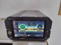
All of this is put in a rack box, in aluminum. The TIP35 can heat a lot and the casing is used to cool it down. 2 USB (one 3.0 and 2.0) and the network are extended to the back panel. .
Some 3D printed support was done, one for the battery, 2 for the display, one for the Raspberry pi.
The schematic and a PCB are on going to be design.
I expect this to be one of the best power supply for Raspberry Pi... Can be great with an HAT DAC.
Laurent
I transferred many Cd on an SSD and use the Pi to send the audio flux to my original AudioNote DAC. For the embedded Pi software, Volumio is used, with a 5 inches screen with touch panel..
However, for this device, I wanted to design a good power supply, with no noise or as less as possible.
The main idea here is to use a lead battery, 6V 12Ah to power the Pi. The measurement I made showed that in this configuration, without internal DAC, the consumption is 1A more or less. So, with a 12AH battery, it can give 12h autonomy. But as the Pi can use up to 3A, the power supply need to be design for 3A.
Based on this, I developed 4 main boards, one for charging, based on LM317 and TIP35 (3A lead battery charger) , one for the power of the Pi, one for the 12V in and the relay to power the charge module and the last one is an MCU to control all..
The original idea was to use comparators logics to manage the charge and the power on of the Pi.. But, with all the functions I wanted, an MCU was better to handle all different functions.
So, the main features of this project is:
- Manage the charge of the lead battery. When the Pi is ON, the charge starts at very low level of the battery (5.35v) but if the Pi is OFF, the charge starts earlier, like 6.4v
- Manage the switch ON and OFF of the Pi with a push button and long press
- Display battery level on 2 leds, with 6 levels (fix and blinking leds)
- Display charge status (charge on r finished)
- The charge is launch through a relay and the command uses an optocoupler to have no link with the external power supply
Charging module:
- Based on LM317, TIP35 for the high current, and current limited with an 0.2 ohm resistor
- The 0.2 ohm is in // with a Vbe of NPN transistor which limit the current.
- The value of 3A is coming from the battery: 12AH / 4 = 3A, charging recommended value for this lead battery.
- There is a 6A diode to avoid the battery to discharge and power back this module. 6A because the worse case is 3A to charge the battery and 3A for the Pi.
Raspberry Pi power supply:
- This power supply need to be low dropout, adjustable
- The specification of the Raspberry Pi V4 is the lower voltage must be 4.75v. To have some margin, the output voltage will be adjust to 4.85v
- 2 different IC was tested. As the battery is 6V and the Pi need 5v, a very low dropout at 3A is needed. Not so many choice. I tried LT3083 which works well but no enable/shutdown function. So, a switch mosfet need to be added which increase the total dropout
- Finally I used the LT1764A, which is adjustable, 3A, low dropout, and with an shutdown pin.
The measurement showed that even at very low level battery, 5.35v, the IC still deliver 4.85v at 3A output. Perfect.
- Another IC possible, but does not try yet is the MIC29302 which is also 3A, enable pin, 0.6V dropout at 3A.
12V Command power module:
- To avoid any kind of switching module inside the device, the input is 12V, from an external 12V 6A power supply
- An 12V relay is connecting the input to the charging module when the MCU commands it.
- To avoid direct link from outside 12V and MCU and battery power, the command is done through an optocoupler
- If the MCU is off, because per example the battery is too low, the relay will be automatically switch ON and power the charge
- One contact of the relay is to shunt the 0.2 ohm current sensor while not charging. without that, the battery level will reduce 0.6v during normal Pi operation (under 3A consumption)
MCU module:
- The MCU is a PIC 18LF2420, with a 3.3v regulator
- It is power by the battery directly
- The software (Mikro C) monitors the battery voltage, the Raspberry Pi voltage, the charging voltage
- It will also manage the push button, manage the relay and the 4 leds (3 leds for charging indicator and one for charging status)
Mains software features:
- Control the charge of the battery: launch and stop charge
- Level of launch charge depends if the Pi is ON or OFF
- When the Pi is OFF, short press on the button display the battery level
- When the Pi is ON, short press on the button with toggle the charge (OFF is ON or ON is OFF)
- Long press on the button will toggle the Power to the Pi
- If the Pi voltage went below 4.75v, stop the Pi and force the charge
- If battery voltage goes over 7.35, force stop charge
- Display full time battery level when the Pi is ON with 6 levels: green, blink green, yellow, blink yellow, red, blink red
- A red LED indicates the charge status: fast blink means charge is needed but no 12V input. Slow blink means charging. Fix red means charging is almost finished
All of this is put in a rack box, in aluminum. The TIP35 can heat a lot and the casing is used to cool it down. 2 USB (one 3.0 and 2.0) and the network are extended to the back panel. .
Some 3D printed support was done, one for the battery, 2 for the display, one for the Raspberry pi.
The schematic and a PCB are on going to be design.
I expect this to be one of the best power supply for Raspberry Pi... Can be great with an HAT DAC.
Laurent
Updates van de auteur