
Remote-Controlled Door Lock
Anyone capable of holding a screwdriver can build this door lock.
It is not very complicated to control a servo with an Arduino and then attach the servo to a sliding bolt. However, making it remote-controlled requires a bit more work.
Remotely controlling over Bluetooth or Wi-Fi is possible, but that implies creating an app for a smartphone or building a web interface and I didn’t want to go into that.
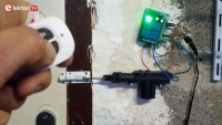
An nRF24-based solution would be nicer but then also you must build a remote control. This is doable, of course, but requires engineering. Infrared would be an option, but then you must point the RC at the lock, which is inconvenient. So, I started thinking of another approach. Use Car Parts for Your Home Probably one of the most common use cases for remote-controlled locks are cars. Today, every car has a central locking system with remote control. It is easy to find spare parts for these systems and I bought a car lock servo online for less than € 10.
It comes with a metal rod for which is for pulling and pushing the lock and some screws. The servo has a travel of approximately 2 cm and, as a nice extra, it is waterproof. The metal rod is about 20 cm long and has a diameter of 3 mm. It is strong enough to function as a bolt, so that is basically all you need to make a door lock. But, if you prefer, you can attach the rod to a real bolt instead.
For a remote control for the lock, we can go about the same way. On the internet you can find very cheap remote-controlled relays intended for garage door openers, motors and pumps and similar applications and they come with a nice keychain remote control including batteries. They look much better than anything I can build myself. Some of them even come with an enclosure for the relay.
These modules have three operating modes:
You can achieve this with two SPDT relays (see schematic below). When idle, both sides of the servo are connected to GND and nothing happens. When the relay on the left is activated, the left side of the servo is connected to plus while the right side remains connected to GND. The servo will move.
When only the relay on the right is activated, the right side of the servo is connected to plus while the left side remains connected to GND. Now the servo will move in the opposite direction.
You can use two wireless single-relay modules because these modules can be set up to use the same remote control. The remote control has two buttons, you can use one button for module A and the other for module B.
There also exists multi-channel versions of these relay modules. I found a 4-way remote-controlled relay for the same price as one of these single-channel modules. With such a module, you can control two door locks or control one door lock and some lights for instance.
Make sure that your relay module works from 12 V so that you need only one power supply for both the servo and the relay. Power Supply For the power source you have several options, like a power adapter, or a car or motorcycle battery or a bunch of AA batteries.
My servo has a DC resistance of only 2.3 Ω and so it will pull a lot of current if it can. Therefore, you would want to keep the on/off pulses as short as possible.
For battery operation I would recommend a 3-cell 3S Li-Po battery of 11.1 V, but in that case, you will also need a good Li-Po battery charger.
Actually, the servo behaves somewhat nicer when the power supply voltage is reduced to 9 V. The relay modules work from 9 V too. This would work with six AA batteries (a PP3-type 9 V battery will probably not have enough oomph fo this application).
Remotely controlling over Bluetooth or Wi-Fi is possible, but that implies creating an app for a smartphone or building a web interface and I didn’t want to go into that.
An nRF24-based solution would be nicer but then also you must build a remote control. This is doable, of course, but requires engineering. Infrared would be an option, but then you must point the RC at the lock, which is inconvenient. So, I started thinking of another approach. Use Car Parts for Your Home Probably one of the most common use cases for remote-controlled locks are cars. Today, every car has a central locking system with remote control. It is easy to find spare parts for these systems and I bought a car lock servo online for less than € 10.
It comes with a metal rod for which is for pulling and pushing the lock and some screws. The servo has a travel of approximately 2 cm and, as a nice extra, it is waterproof. The metal rod is about 20 cm long and has a diameter of 3 mm. It is strong enough to function as a bolt, so that is basically all you need to make a door lock. But, if you prefer, you can attach the rod to a real bolt instead.
For a remote control for the lock, we can go about the same way. On the internet you can find very cheap remote-controlled relays intended for garage door openers, motors and pumps and similar applications and they come with a nice keychain remote control including batteries. They look much better than anything I can build myself. Some of them even come with an enclosure for the relay.
These modules have three operating modes:
- Momentary – press for on, release for off;
- Latching – press one button for on, press the other for off;
- Toggle – press for on, press same button again for off.
You can achieve this with two SPDT relays (see schematic below). When idle, both sides of the servo are connected to GND and nothing happens. When the relay on the left is activated, the left side of the servo is connected to plus while the right side remains connected to GND. The servo will move.
When only the relay on the right is activated, the right side of the servo is connected to plus while the left side remains connected to GND. Now the servo will move in the opposite direction.
You can use two wireless single-relay modules because these modules can be set up to use the same remote control. The remote control has two buttons, you can use one button for module A and the other for module B.
There also exists multi-channel versions of these relay modules. I found a 4-way remote-controlled relay for the same price as one of these single-channel modules. With such a module, you can control two door locks or control one door lock and some lights for instance.
Make sure that your relay module works from 12 V so that you need only one power supply for both the servo and the relay. Power Supply For the power source you have several options, like a power adapter, or a car or motorcycle battery or a bunch of AA batteries.
My servo has a DC resistance of only 2.3 Ω and so it will pull a lot of current if it can. Therefore, you would want to keep the on/off pulses as short as possible.
For battery operation I would recommend a 3-cell 3S Li-Po battery of 11.1 V, but in that case, you will also need a good Li-Po battery charger.
Actually, the servo behaves somewhat nicer when the power supply voltage is reduced to 9 V. The relay modules work from 9 V too. This would work with six AA batteries (a PP3-type 9 V battery will probably not have enough oomph fo this application).
Want to build a project?
Bring your design to life with the Elektor PCB Service, powered by Eurocircuits. Upload the project files and order professionally manufactured PCBs or assembled boards through a proven European production platform.
Supporting KiCad, Eagle, Gerber, and ODB++ formats, the service is suitable for everything from prototypes and validation builds to series production and volume manufacturing.
Made in Europe. Fast. Reliable. Professional.
Discussie (1 opmerking(en))