
Simple Air flow detector circuit
This circuit can be used to give visual indication of the rate at which the air flows. It can be applied also to indicate whether the air is flowing in a given place.
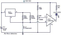
In this project, i shall be using a filament of an incandescent bulb as my sensing part in the circuit that I shall build. When the air flow shall be zero, the filament resistance will be low and when the air flow is available, the filament resistance will of course drop simply because the air flow will remove the excessive heat that will be generated from the filament. The variation in the resistance will lead to a variation in the voltage across the filament. The said variation will be picked up by the op-amp and the brightness of LED at the output will be varied proportional to the flow of the air.
- Make filament L1 by removing the glass of a brand new incandescent lamp.
-Power the circuit Using the 12V DC battery or power supply
You can design a regulated power supply with LM317, as it provides variable output depending on the value of variable resistor attached at its output pin.
- Make filament L1 by removing the glass of a brand new incandescent lamp.
-Power the circuit Using the 12V DC battery or power supply
You can design a regulated power supply with LM317, as it provides variable output depending on the value of variable resistor attached at its output pin.
Want to build a project?
Bring your design to life with the Elektor PCB Service, powered by Eurocircuits. Upload the project files and order professionally manufactured PCBs or assembled boards through a proven European production platform.
Supporting KiCad, Eagle, Gerber, and ODB++ formats, the service is suitable for everything from prototypes and validation builds to series production and volume manufacturing.
Made in Europe. Fast. Reliable. Professional.
Discussie (1 opmerking(en))