
Simple electronic lock
An electronic lock can use a keyboard, fingerprint scanner, RFID etc. This one uses a simple potentiometer to enter the secret code.
Operation
To open the lock the potmeter is set to the the first symbol of the secret sequence and the button is pressed. Then the second one etc. After entering the last symbol (if all were correct) the output becomes active and the lock is opened.
The sequence is saved in the EEPROM of the microcontroller and can be changed in the same way with the potmeter and the switch. To enter a new code connect jumper JP1 and press reset. The circuit will report the activation of the setup mode by a short pulse on the ouput. After every press of the button also a short pulse on the output will appear. If you are done with the codes just remove the jumper and press reset again. The sequence can be as long is the EEPROM of the microcontroller (256 bytes), but I limited it to 50 bytes (who can remember that much?).
Hardware
Only a few components are needed to realize this simple electronic lock.
A potentiometer and a pushbutton are used as input devices and a small microcontroller is the heart of the circuit. On the output side a mosfet is present, which can operate the coil of a relais or doorlock.
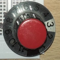
On the potmeter axis a knob with an arrow or other indication is mounted and a scale with (for instance) 10 numbers or other symbols.
Because the current consumtion is very low if in rest, one could use a battery as power supply (between 3 and 5 Volt will work). If mains operation is used, the power for the microcontroller circuit can be provided by a 78L05 or similar device.
The microcontroller used is a PIC12F1840, but a PIC12F1822 should also work.
At this moment there is no PCB available, because I "misused" an existing PCB for my circuit.
Software
The program is very basic and simple: the EEPROM contains the 8 bit AD-values of the consecutive numbers. If the button is pressed, the AD-value of the potentiometer is compared to the according EEPROM location. If the difference is within a certain limit, the number is accepted and the next one can be entered. If the number is wrong or the time-out of 4 seconds is over, the microcontroller is put to sleep and waits for the start of the next try. In this situation power consumtion is very low.
New PCB
This project can be build on the PCB described: here as the newPCB photo shows. I added a partslist to summarize which parts have to be used. A separate drawing is added to show how the potentiometer and the key are connected to the board.
Because some microcontroller pins have been swapped and because of changed polarity of the jumpers a new version of the program is needed. The old hex-file is included in the zip-file and you can compile the source with the original pinning if you undefine "PCB_UNI".
The board can be assembled for 5V or 12V (se partslist). The 5V version is shown in the newPCB picture. The supply for this board is coming from 3 alkaline cells. Stand-by current of my board was 15uA.
To open the lock the potmeter is set to the the first symbol of the secret sequence and the button is pressed. Then the second one etc. After entering the last symbol (if all were correct) the output becomes active and the lock is opened.
The sequence is saved in the EEPROM of the microcontroller and can be changed in the same way with the potmeter and the switch. To enter a new code connect jumper JP1 and press reset. The circuit will report the activation of the setup mode by a short pulse on the ouput. After every press of the button also a short pulse on the output will appear. If you are done with the codes just remove the jumper and press reset again. The sequence can be as long is the EEPROM of the microcontroller (256 bytes), but I limited it to 50 bytes (who can remember that much?).
Hardware
Only a few components are needed to realize this simple electronic lock.
A potentiometer and a pushbutton are used as input devices and a small microcontroller is the heart of the circuit. On the output side a mosfet is present, which can operate the coil of a relais or doorlock.
On the potmeter axis a knob with an arrow or other indication is mounted and a scale with (for instance) 10 numbers or other symbols.
Because the current consumtion is very low if in rest, one could use a battery as power supply (between 3 and 5 Volt will work). If mains operation is used, the power for the microcontroller circuit can be provided by a 78L05 or similar device.
The microcontroller used is a PIC12F1840, but a PIC12F1822 should also work.
At this moment there is no PCB available, because I "misused" an existing PCB for my circuit.
Software
The program is very basic and simple: the EEPROM contains the 8 bit AD-values of the consecutive numbers. If the button is pressed, the AD-value of the potentiometer is compared to the according EEPROM location. If the difference is within a certain limit, the number is accepted and the next one can be entered. If the number is wrong or the time-out of 4 seconds is over, the microcontroller is put to sleep and waits for the start of the next try. In this situation power consumtion is very low.
New PCB
This project can be build on the PCB described: here as the newPCB photo shows. I added a partslist to summarize which parts have to be used. A separate drawing is added to show how the potentiometer and the key are connected to the board.
Because some microcontroller pins have been swapped and because of changed polarity of the jumpers a new version of the program is needed. The old hex-file is included in the zip-file and you can compile the source with the original pinning if you undefine "PCB_UNI".
The board can be assembled for 5V or 12V (se partslist). The 5V version is shown in the newPCB picture. The supply for this board is coming from 3 alkaline cells. Stand-by current of my board was 15uA.
Want to build a project?
Bring your design to life with the Elektor PCB Service, powered by Eurocircuits. Upload the project files and order professionally manufactured PCBs or assembled boards through a proven European production platform.
Supporting KiCad, Eagle, Gerber, and ODB++ formats, the service is suitable for everything from prototypes and validation builds to series production and volume manufacturing.
Made in Europe. Fast. Reliable. Professional.
Updates van de auteur