Spot welding [130286-I]
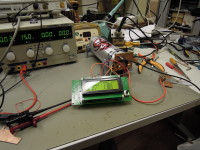
A few years ago Elektor published a workshop on spot welding for smaller objects (welding battery packs) using capacitive discharge. This was not a finished project, rather a starting point for experiments and development.
A few years ago Elektor published a workshop on spot welding for smaller objects (welding battery packs) using capacitive discharge. This was not a finished project, rather a starting point for experiments and development. Professional equipment for making and fixing jewelry is really expensive and complex (including shielding with inert gas, microscope with electronic shutter etc.), for now I'm just looking and investigating what is really needed in my project. Any suggestions?
Discussie (14 opmerking(en))
gazza154 5 jaar geleden
i would suggest using a microwave Tx with the secondary removed and replaced with a few turns of 6-10 mm insulated cable to produce 3-5 volts ac.
To control this a SSR is used on the primary and can turn on/off and Pwm for power adjustment using a micro or 555 timer.
This is a way to test spot welding and work out the voltage,time and power needed for good welds.
With usable specs then the caps and voltage needed to charge and the time for discharge can be calculated.
There are many designs on the web but I could provide photos and circuit for a Tx version at least !
Gary
Arthur Cloet 9 jaar geleden
I saw this technique tens of years ago, and it works...
It was used to weld thermocouples to steel parts.
basically, some capacitors (few microfarads, regular stuff) was charged to 220V (dc, of course, so much more) and with an ordinary switch discharged while the isolated handle kept the thin wire of 0.5 mm at its place. A huge spark showed that it was NOT succesful, but an almost invisible spark indicated success.
So I wanted this to weld wires to NiMH cells too, at home this time....
A defective regular welding invertor did the trick: 220V rectified, a big capacitor of +\- 300 uF and a contactor (relay) of 25 kW switching capacity made it possible to weld hundreds of batteries. To charge this circuit and to avoid high CONTINUOUS current I charged via a halogen lamp of 500W and meanwhile I cut off supply while welding. A foot switch gave me some extra freedom. The electrode (handle) was an old carbon brush of an electric motor: it does not stick to the welded wire.
So no software or expensive parts were used....
Did I explain already to be careful??? 220V is lethal, so be Extremely careful. And molten metal sparks can burn holes in your eyes, so take precautions. No kids allowed.
More info? Let me know.
Welding bigger wires? You might need 10 000A or more. Been there, did it, succesful too, even less dangerous. I had an old (also) defective welding transformer, stripped the primary winding and replaced it by 3 (three) windings of +\-150 square mm isolated copper wire or more. I lead this to the metal sheet to be spot welded via copper bars. The "secondary" winding was then fed by a Working welding transformer (not an invertor, as they give DC or AC with a too high frequency)
Giving enough pressure while switching on the first transfo gave me perfect welds. Some tuning might be necessary.
gazza154 5 jaar geleden
terre terre 9 jaar geleden
i drawed a scheme, is it correct ? http://hpics.li/cac5bf9
and thanks
Lucky 9 jaar geleden
This week the capacitors arrived, two 1F of a different brand than the first one. Hope these two will last longer than their predecessor.
The picture shows them both, the right one still with its fancy LED display, the other just the bare capacitor like we will use it for our spot welder. Admit it: with the display it looks much more impressive, and it will absolutely improve the sound quality of your car audio system much more than the one without the LEDs ;-)
This time we started measuring capacitance before welding, just the charging curves of 1F with a 10 Ohm resistor in series. As you can see from the scope plots both capacitors are well within 10% tolerance, one of them a bit more and the other one a bit less than 1F.
Now it's time to connect them to the CD welder and see if and how they work and -even more important!- if they keep working. We'll see...
2khz07.PNG (7kb)
2khz08.PNG (7kb)
Lucky 9 jaar geleden
Suddenly the quality of the welds was much less than before… It was absolutely clear that there was much less power in our welder than before, when the welding was audible/visible and the cables between the capacitor and the electrodes moved when the welding was triggered. We didn’t measure the true capacitance of our 1F capacitor when we started the experiments (and yes: we should have done that), but it turns out that now there’s only 500mF left. Apparently this capacitor was not designed to source peak currents of around 200A, and some internal damage must have caused this loss of capacitance. We are planning to open it up to see what’s inside and look if we can discover what went wrong, but we will take some precautions in this don’t-try-this-at-home-operation, electrolyte can be nasty stuff.
But still: how to proceed? Buying exactly the same capacitor and trying again is no option, it would be silly to assume that it was just bad luck. Moreover the 1F capacitance didn’t really work that great, we need some more power. In our first tests we saw that the voltage at the capacitor already dropped considerably after a 1ms pre-weld pulse (e.g. from 11V initial charge to 9V), leaving (probably?) too less energy for the second welding pulse. However, we were not disappointed with the strength of the joints, it took quite some force to tear the pieces of metal apart, leaving a hole at the point where the weld was made.
Of course there are other options for spot welder designs, like using a transformer or battery as source for the welding current, but we were aiming to design a capacitive discharge welder and it should be feasible. A design using an battery would come close, but that would call for extra safety measures in case of failure: you don’t want any battery permanently shorted….
Back to the new capacitor. If we settle for 2F capacitance, let’s consider the options we have.
We always have to keep an eye on price and (maybe even more important!) availability of components used in Elektor projects. Specifically for this project the latter means that we can’t look for capacitors on auction sites or electronics surplus (web)shops. Off the shelve big capacitors from our preferred suppliers are no option from a financial point of view.
If we stick to car audio capacitors (most affordable option), we will still face the lack of electrical data. Still there are many CD welding projects on the internet using these capacitors and the designers claim that their welder works great, or did they stop blogging before the capacitor failed?
There are some reports on the internet of people who did some measurements on these capacitor, unfortunately the brands/models tested are no longer available and/or not for sale here in Europe, so that didn’t help much. The looks, physical dimensions and even the manuals with the scarce electrical data… they all look alike. Two 1F capacitors in parallel will lower ESR and will distribute the welding current between the caps, sounds better than using just one 2F capacitor. Let’s give it a try…
Lucky 9 jaar geleden
Spot welding can be used to in many applications ranging from making jewelry to assembling vehicles, we decided to make a welder suitable for welding metal tabs on battery packs, which is –in our opinion- the most common application of this bonding technique in electronics. On the internet you can find many DIY projects for this purpose, but of course we wanted to design one ourselves..
We decided to build a welder based on the principle of capacitive discharge: the energy stored in a big capacitor (bank) is used to weld two pieces of metal together. Apparently a better weld is made in three phases: one short pulse to heat (soften) the metal and clean the spot where contact between the metal parts is made, and the second pulse to make the weld. During the pause between both pulses (often referred to as ‘dwell’), the parts come closer together and make better contact.
But first some warnings about this project:
From other examples on the internet we learned that a capacitance of 1F or more, charged to a voltage in the range of 10 to 20V should do the trick, we used these assumptions to start with our spot welder. Please bear in mind that all parameters in this project are highly dependent on the size and composition of the objects you want to weld.
Designing a controller for a dual-pulse capacitive discharge welder is not exactly rocket science. It should allow the user to adjust the pulse voltage(steps of 1V), the pulse times for pre-weld and weld and the pause between the two pulses (times in increments/decrements of 0.5V). It measures the voltage of the capacitor(s) and charges/discharges to set it to the correct level, and of course controls the switching of the welding pulses when a trigger (foot-) switch is pressed.
The first version of the controller was built on a Platino-board, with a ATmega328 microcontroller holding an Arduino bootloader, a 2 x 40 character alphanumeric LCD plus a rotary encoder. The lower-current hardware for (dis-)charging the capacitor was constructed on a Platino Add-On board.
The most tricky part is welding circuitry, which consists of the welding capacitor(s), power MOSFET(s) to switch the welding current, the electrodes and –last but not least- the interconnections between these parts. For spot welding we need high current, and in the ideal world the only resistance/impedance in the discharge path of the capacitor would be at the point where we make the weld between the two pieces of metal. It’s difficult or even impossible to build this part of the welder on a PCB and to be honest: in this case it’s even better. With this part of the circuit built with sturdy wiring it’s relatively easy to change the component without redesigning the PCB layout. And we must admit: there were some high current c.q. high power phenomena not taken into account in the first steps of the design. Still this is not completely true: the switching FETs we chose are SMD types, and we made a simple and small PCB that fits directly on the capacitor to mount these components.
First of all, and the key component of this project: The Capacitor, (or capacitor bank if you want to connect more of them in series or parallel but in all cases we will refer to it as ‘capacitor’). For spot welding you need an ESR as low as possible, power loss inside the capacitor will lead to less energy for making the weld.
For welding battery tabs (and similar smaller pieces of metal) the capacitance should be at least 1F, preferably even 2F or more. We’ve seen some projects where high capacitance, low voltage capacitors are connected in series to reach the voltage required, but this has some serious disadvantages like adding up ESRs and balancing of charge of the capacitors.
Connecting capacitors in parallel sounds more promising, as the total ESR is lowered with every extra capacitor added to the circuit. We haven’t tried this yet, but it may have the negative side effect that one (or more) capacitor is more stressed than the others during discharging, eventually leading to damage of this component.
We decided to start with the most affordable choice: one big 1F capacitor. There are many of these available in the car audio market at a reasonable price. For the time being we took for granted that the ‘datasheets’ of these parts only show maximum voltage, the capacitance and the physical dimensions. Not a single word about ESR, peak current or other relevant data, only some big talk how it will improve the sound of your car amplifier…. The first modification we did was to remove the LED voltmeter that was mounted on the capacitor, it looked nice but didn’t serve any purpose in our project and –more important- it keeps discharging the capacitor.
We didn’t focus on the charge time of the capacitor (yet), making reliable welds is our main concern. For the time being its charging current is simply limited by a resistor and it takes a while before the capacitor is recharged after a weld is made.
Switching the discharge current
In our design the welding pulses are switched with MOSFETs. This application requires FETs with low Rdson and -of course- high drain current. For the BSC010NE2LS the specs are 1mOhm for the Rds and 100A continuous drain current (pulse even higher), but to stay on the safe side we put five of these in parallel. Still we succeeded in transforming FETs into short circuits during welding, quite scary when you put the welding electrodes on the metal and get an uncontrolled discharge of the capacitor even before the trigger switch is pushed… It appeared that it wasn’t the current pulse itself that killed our FETs. The welding leads plus electrodes form an inductance that leads to high transient voltages when the discharge path between the electrodes gets interrupted. A fast free-wheeling diode (FFPF30UP20ST from Fairchild) between the connections of the leads solved this issue.
The FETs now only have some cooling from the copper plane of the PCB they are mounted on (see picture). In other welding projects on the internet we see massive cooling for the switching FETs, but we have the impression that this is a bit overkill with the pulse lengths of only 10-20 ms and the low repetition rate of subsequent welds we made until now (note that there is a recharging time of a couple of seconds).dscn44511.JPG (2045kb)
dscn44481.JPG (1840kb)
Lucky 9 jaar geleden
I took quite some time since I started this project, but during the last weeks I finally took the time to start with a real working prototype. I started testing, even made some welds, killed a few MOSFETs and it looks like my first 1F capacitor doesn't like the way it is treated in this project :-(
More to follow later on this day.
sdukester 11 jaar geleden
I have made a working cap discharge system with which I have spot welded hundreds of decent 0.6mm dia steelwire joints and superb welds on 0.8mm stainless steel wire.
5* IRFP3206 HEXFET Power MOSFET with a Pulsed Drain Current of 840 amps from farnell on a very low ohm(heavy copper bus bar wiring) This allows thousands of amps at the selected voltage for the amount of miliseconds set to be discharged from a 1 farad capacitor. As you can guess the critical factor is the resistance of the whole current path. Control is by the voltage the capacitor is charged to and the length of pulse giving the amount of power discharged. An 18F877 pic micro provides the charging control and times the firing pulse then displays the power used on the last weld pulse.The initial voltage the capacitor was charged to minus the voltage left in the capacitor times the capacitance gives the amount of power actually discharged (easy calc with a 1 F capacitor). The display of power gives a good indication of the weld energy allowing for the resistance of the welding 'clamp'.
Future advancements would be dual pulse to clean up the weld area first
then a main welding pulse to produce a consistent weld in copper etc. ( essentially a simple software mod along with another pot to set and a switch to select this mode). Inert gas / microscopic viewing and fine control to weld microscopic wires (control of the charge/ discharge of the essentially capacitive gates of the fets) are more complicated but still possible given the need / budget for such a functionality. An rough outline of the key items is shown in a diagram attatched showing the main parts without charging circuit or dividing networks for the adc inputs etc. This diagram was purely for the illustration of the i/o for programing purposes not a full circuit diagram. The fets are shown with the low ohmic connections (lots of copper) 'bus bar' setup, although ugly it works. A pic of the outside of the unit with the set of welding tongs used for welding wire together. Lastly a pic after a dummy weld without a charge on the capacitor. The main cost of the unit for me was the 1f capacitor from Tandy and the fets from Farnel, having managed to scavenge most of the other bits.
fets-with-bus-bar-wiring.JPG (109kb)
spot-welder-with-tongs-used-for-wire.JPG (113kb)
spot-welder-after-trigger-with-no-charge-on-capacitor.JPG (92kb)
Lucky 11 jaar geleden
Clemens' idea of using LIPO cells instead of capacitors is quite interesting, although other people are very reluctant to use them for this application. As we all (?) know, shorting batteries -especially the one's containing Lithium!- is a very dangerous sport. There are lots of demonstrations to be found on the internet how NOT to handle LIPOs (like http://youtu.be/6vYn2lbBh0Q). Of course, the control electronics will limit the welding time to a few milliseconds (two subsequent pulses) and I assume that wil do no harm to the battery. Even more important: if I limit the welding pulse time, the battery won't harm me!
A commercially available balancing charger for cells will be used to charge the cells, so that will (at least for the time being) no part of this project. First, let's try if this concept will work.
For the brains, time keeper of our welder, an existing microcontroller board with some push buttons and LCD will be used for the initial firmware design and experiments. The power electronics, i.e. the FET's switching the welding current on/off will be on an extra PCB or even hard wired.
Lucky 11 jaar geleden
Looked at some DIY projects on the internet, basically all the same concept. One important issue is chosing the right capacitor (pack). Some use a pack of capacitors in parallel (lowering ESR and increasing capacitance), others rely on one big capacitor, like the 1F or more types used for car audio.
Both solutions cost about the same, but which of both will work better, and which will last longer? Even if we control the welding (=discharging) time to very short pulses, it will eventually degrade and even kill the capacitors. Gut feeling says that sharing the pain of shorting between a bunch of capacitors will let them live longer than one capacitor doing all the work (?).
One thing about the 'car capacitors', I have the feeling that most of them are made to look good and expensive, but in most cases the electrical data is limited to capacitance and max. voltage. If you want to know if they'll fit into your car and if they will match with the colours of the interior, you'll find more extensive info...
Anyway, I'm not sure yet what the best choice will be, any suggestions, or other things to consider?
plasmaboog 11 jaar geleden
match depend on what the tickness is of you material but I have build several years ago a spot welder for tho weld stainless steel of 0,2- 0,3 mm and this is whit a transformer whit a voltage from 2 - 6 volt about 200 amps but I can look what the amps are and there stay only a timmer on. look for a old transformer about 1500 watt and rewind it wit welding cable off 50mm² make that you have volt selection of 2,3,4,5and 6 volt and look for a timer you can start whit a pusch on the button when you have make the connection beween the 2 plates
whit to play whit the time and volt you will find the right solution for you welding problem?
benny
Heinz-Peter 11 jaar geleden
Hey Lucky,
I hope it`s not to late to give you a suggestion for Capacitor Discarche Welding.
You need some high capacitance capacitors (E=1/2 SQR U C), a transformer, a thyristor with ignition circuit and spring forced electrodes.
Voltage on primary side 50V and secondary 5V should be ok for small parts.
Capacitor discharge means a high current peak transformed to a much higher peak, current flow time a few milliseconds.
If you want to know more about CDW give me a wink a I can do some calculations for you. 15 years experience in resistance welding.
Lucky 11 jaar geleden
ClemensValens 11 jaar geleden
Hi Lucky,
For 10 euros you can buy pretty high-capacity li-po battery packs. They can do 25C easily, meaning that you can get 25 A peak from a small 1 Ah battery. Isn't that enough?
Regards,
Clemens
NECV20 11 jaar geleden
In the Elektor article, 'normal' capacitors of 10000 uF are used.
But more capacitance can be stored in a goldcap.
For example Goldcap elco NF-TYPE 1,0F 5,5V.
And they are even cheaper (2,83 euro) than the ones used in the Elektor article
The only difference is that the goldcaps must be placed in series.
Six of them can 'take' up to 33 Volts.
Normally the goldcaps are used as a battery backup.
But can they be discharged fast enough to make the spark?
NECV20 11 jaar geleden
I reread the article you mentioned. It looks rather complete.
What you really need are the capacitors (8 or may more), BUZ11's (4 or more) and the transistors BC550 and BC560.
Problably a BC547 and BC548 will work just as well.
And then of course the weldelectrodes. Use some you can spare.
In the original design a ATTiny13 is used for the trigger and ignite sequence. But here you are free to use something else. The ignitepulse is given by making the base of BC550 high.
I myself am thinking of using a footpadel. That leaves my hands free.
The whole circuit with the 7805 and ATTiny can be left off. The pedal makes a contact between + en R7 (where in the schematic the contact PB2 of the ATTiny is). Do not use the contact of the footpadel in the circuit with the weldelectrodes because then you would weld the contact in the footpadel.
Jan. 2013 - and I built it too. With my favorite housing material - wood from sigar boxes (yes, I am a sigar smoker).
See the photo's, schematic and the lochmaster (great program!) PCB design.
picture2.JPG (517kb)
Printlayout.pdf (122kb)
The lochmaster project file (338kb)
Lucky 12 jaar geleden