I designed and built a fully transparent Arduino UNO‑compatible board on a flexible PCB; no copper pours, no hidden layers.
This is a fun project where you can literally watch the electrons flow (okay, not really, but you get the idea! ).
This trensparent board runs standard Arduino sketches, includes a 3x3 NeoPixel array, and is reinforced with a 3D‑printed transparent resin frame to make the flex board rigid. The best part? All design files are open source and free.
I started in Altium Develop by creating a schematic based on the classic Arduino UNO.
Key choices:
ATmega328 as the main MCU
CH340 for USB‑to‑Serial communication
3x3 NeoPixel matrix for visual feedback
NE555 timer to drive a fading power LED
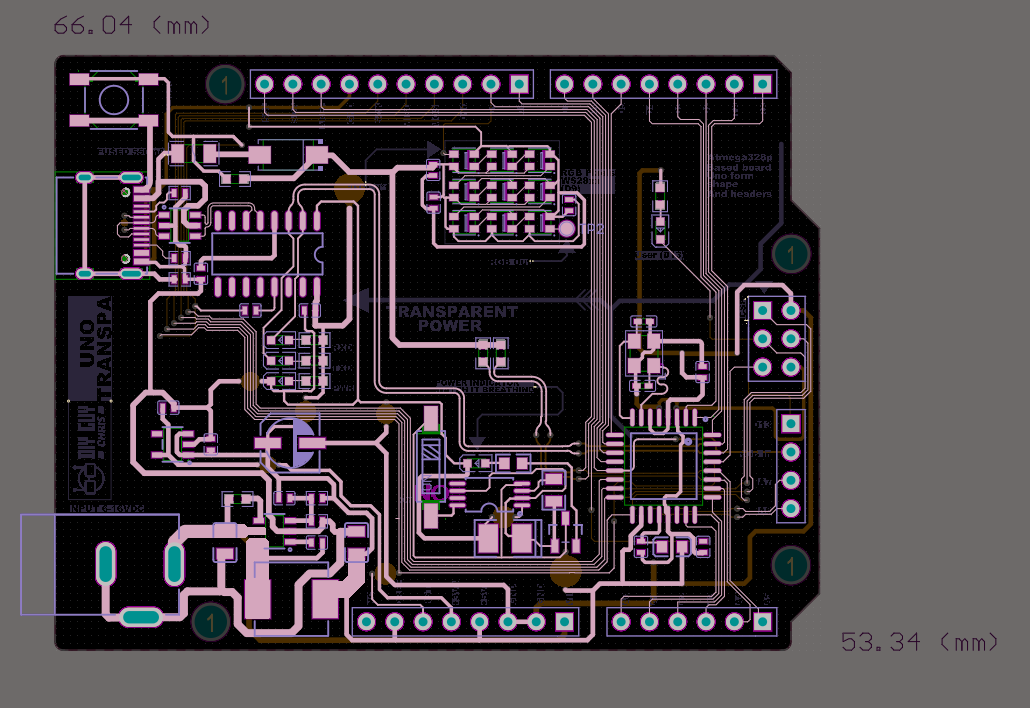
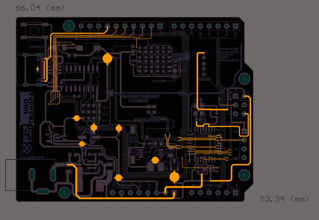
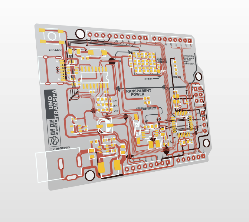
Then I converted the schematic into a PCB layout. The board outline matches the original UNO size. The most important rule? No copper pour regions! that would block transparency. I routed all GND and VCC nets as visible traces.
You can explore the full design online via Altium 365 – check this link for accessOrder the Transparent Flex PCB & Resin Frame
I uploaded my Gerber files to JLCPCB and selected (Download the GERBER Files from here):
Material: Flex
Substrate type: Transparent
Stencil: Yes (custom size)
A few days later, the iconic blue box arrived with perfectly manufactured transparent flex PCBs. You can literally hold them up to the light and see every trace.
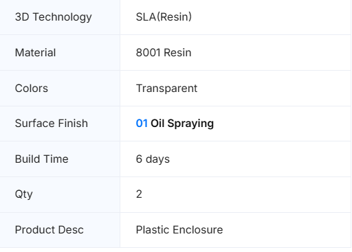
For the rigid frame, I uploaded an STL file to JLC3DP with these settings:
Parameter Selection
Technology SLA (Resin)
Material 8001 Resin
Color Transparent
Finish 01 Oil Spraying
You can get the board ready assembled from JLCPCB, you need the BOM and Pick&Place files to place an Flex PCBA order.Assemble the Circuit
Solder paste & placement : I taped the flex PCB to my desk, aligned the stencil, applied solder paste evenly, then carefully placed all components using fine tweezers. Double‑check the orientation of the MCU and CH340!
Reflow : I placed the board on a mini hotplate and watched the magic happen through a digital microscope. The paste melts, components settle into place, and a transparent board comes to life.
Through‑hole connectors : Soldered manually with a regular iron. Bonding to the resin frame : The flex PCB is soft, so I glued it to the 3D‑printed transparent resin frame using a thin layer of epoxy. The result is a rigid, crystal‑clear Arduino board.
Program & Test
Burn the bootloader : Using an ISP programmer, I burned the Arduino UNO bootloader onto the ATmega328.
Upload sketches : In Arduino IDE, I selected Board: Arduino UNO and uploaded a simple Blink sketch. The onboard LED started flashing, success! Then I uploaded a FastLED sketch to control the NeoPixel matrix. Colors cycle smoothly across the 3x3 grid, visible right through the transparent board.
That’s it, a fully functional, transparent Arduino UNO on a flexible PCB!


Discussie (0 opmerking(en))