
Universal Battery Charger
A multi chemistry charge for 4S packs and 12v lead acid cells, with balancer an temperatur monitoring
This project discibes the way on building a multi chemisty battery charger, and the way the hardware and softwaredepetment worked to get this done.
In the first spot we considered adding a sd-card slot to the system for logging and storing charging recepies for your rechargible battery packs, but skipped it, as the same feature can be relized through the webserver and internal flash without the hassel of bad connecting sd-cards. The ESP32 can store files in the SPIFFS and we can reserve a few kB for user Settings, we also can write during runtime to the flash like you would write to a sd-card.
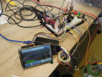
The other poit we needed to discuss was the way we will display the statusinformation of the charger. Ideas went form smartphone only to some leds over to a kind of tff display. We ended up with a prototype using a raspberry pi display and started building a UI with littlevgl as graphic library. This will give the user a nice and graphical way of interacting with a touch frendly interface and we don't have to hassle with may I/O-pins for buttons for the user, and enables us to add later user whises to the system in a way it won't be possible just with a few knobs an a two line and sixteen character display. You may ask why we haven't use the nextion displays in this build, as they requiere only a serial connection and 5 volt. If the user must update the system, is will end up in less hassel if only the ESP32 needs new firmware, and not also the display has to be flashed. Also you have with the nextion display a few less features and possibilitys for your layout as with a generic SPI connected TFT. The raspberry pi TFTs are good avalible and provide a resonable speed.
Besides UI and webinterface the more important part is the charging itself. As mentioned the ESP32s ADC has some weaknesses we added a eight channel I²C-ADC to the system. This gives us a bit better accurancy and also reduces the input pins requierd on the ESP. What we came accross was the question how good the driver for the I²C-controller can handle clockstretching and handle the 400kHz clock we need to the adc. The I²C is working but gave a bit of a headache in the the first place. As the protoype started on several breadbaords we struggeld a bit with power and signalintegrity problems. This results in the I²C-controller recognizing a hung device on the bus and forcing a reset. Also we have encuntered the usual reboots and misbehaving software if the ESP32 is not feeded propper with power although the supply we used culd serve enough current, the cheap wires, with just an idea of coppen in them can't. A few 100nF and 10uF Caps, with a reassambly on only one breadbaord, later, the components and the ESP32 were up and running as expected. Also we were happy to see that the clockstretching that the ADC dose is handled fine and data is collected as it should.
 the main menu. This should be tochfrindly and allow you to change the settings accordingly. At the moment we are using the Littlevgl library in version 5.3 and it seems we need to move now to version 6.0, including cahnges in the API ans some rework in the code. Nevertheless progress is taking place and slowly the parts of the UI become alive. The Wireless part is finished for now and give options we haven't included in the earlier esp32 projects.
You can now choose if it is enabled or disabled, also fore it to accesspoint mode with password protection.
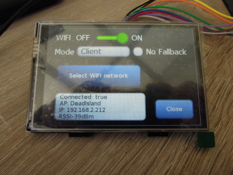 Also some space at the bottom is used to show you the curren state of the wifi network connection. Setting up the charger to wifi shpuld now be an easy job.
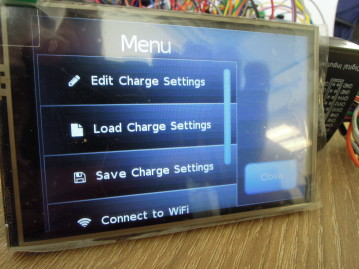
What also has gotten to life is the chargesettings menu. An even if it looks not that shiny, some nice triks are involved.
The simple scenario using only one cell means just charing with a given a current. Not fancy and nothing special. Things you will expect from a basic charger. If we go a bit further we see we can see some more options.
 Balancing is supported and depending on the choosen cell chemistry you also can choose the end of charge voltage. This one is shown for the Lithum based cells. Also the discharge current can be set individually from the charge current.
Well for the Webinterface we need also to add the ability to have some interaction with the device, meaning a recreation of a bunch of menus, also screenshots with the camera are nice but nit the rea deal. So we added a websocket based remotescreen function to the webinterface. Currently limited to view-only mode, but working.
Besides this little goddie making screenshots possible we will add more and more items to the webinterface in the comming weeks.
The nice thing about this, we can later reuse the code to build something one of the developer needs for it 19" rack at home. But first a few screenshots form the UI components:
As you can see, we now are able to select a specific 1-Wire sensor to be used with a battery we like to charge. The values will be fetched from the bus using a seperate thread deleivering us every two seconds a new set of values. If you are on an ESP32 and want to read 1-Wire devices, make sure you use a ESP32 optimized lib, else you will get a lot of garbage, as the code for 1-Wire is timing sensetive, and the RTOS ans Flash-Cache is no help to meet this. For now with four sensors the bus is runnign stable and also reporting if one of the sensors is not found any more. Most of the work is currently done unter the hood, so more nice screenshots are a bit difficult. As the temperaturs are now in place the netx one is to the get the balancer voltage and current for the cells.
The ESP32 is a cheap and powerfull dual core mcu. Looking at the raw numbers ( 240mhz per Core / 4MB Flash and 512kb RAM ) this should be an ideal companion if we want it as core for a battery charger. Other devices have a mcu that is way less powerfull. But there is a catch, specally when doing DC/DC Converter applications like in the battery charger requiered. The ADC is, well, lets be honest, a peace of junk. On paper we have 12Bit Resulution at speeds above 1MSPS, sounds nice, but the results you get are everything but linear. Also the ADC will do some clipping, menaing that we can't messure down to zero volt and also not be able to go upt to 3.3 volt full scale. On the lower side clipping will vvure somwhere arround 0.5 volt and max out somewhere near 2.8 volt. This decreases the range usable to us, to make things even worse the ADC is not working in a linar way. After all you can be happy with many tricks and software correction curves to get in the end near to 8 bit resulution. For many small projects this might be fine, but to decide if we have 4.25 or 4.20 volt in a battery pack, thats someting we won't get from the EPS32. Also running the WiFi will introduce some additional noise to the readings making ugly readings just worst. Last but not least there is one additional catch, that hurts more the audio folks among us, but also has inpact on any other that want to sample data. The analog signals are routed inside the chip throug the IOMUX, so we gain a lot of flexibility, but the price is an analog bandwith of arround 6kHz for signals, as the IOMUX will work as low-pass filter.
This means we will nedd to hook up an external ADC if we want to have usable analog readings and we tested a MAX11614 one, connected via I²C. This gave us usable 12Bit resulution and a decent conversion speed, on paper. In reality we need to deal with some parts of the RTOS runnin gon the two cores limiting the read spead to 200 times a second for four channels with some sideeffects produced by the I²C-Driver used in the ESP32. The next part is the DC/DC Converter, biuld as simple Buck Boost stage controlled by the ESP32. We did some experiments with the statge, and while the Buck part gernerally works, the Boost part was hard to get stable outputting a desired voltage. For the controlloop there are also things like interrupt latency, e.g. you setup a timer to call a function periodically. After the timer fires the interrupt it may takes up to 500 cpu cycles untill you function gets executed. assuming 240Mhz this will lead to 2.1µS delay, a AVR clocked at 16MHz has a simular time to get to an interrupt routine. For controlloops that need fast responses, and a DC/DC Converter is something like this, not ideal. At this point the nasty parts of the ESP32 architecture showed up that heavy, that a change in concept and adjusted it.
Also the balancer part is changed. We still need an ADC and a "small" electronic load to be able to discharge cells in a not to long timespan. The electronic load could be opperated by the ESP32, but an MCU with a 12Bit ADC is not much more expensive that an external ADC with the same amount of inputs. This is why we choos the elektronic load and balancer to become its own module for the moment. This means we can test it independently for the ESP32 and the DC/DC stage and may be able to sperate the developement in its onw E-Load project. The same will be true for the DC/DC converter.
PCB prototypes for the ELoad are on its way and we will hopfully be able to provide first images soon.
First requierments
As with all projects this stated with the idea of having a new multi chemisty battery charger with added abilitys, like WiFi and a nice way to control the userinterface. As chemisty it was decided to support NiCd, NiMh, Li-Ion, Li-Po, LiFePo and lead acid cells and also be able to do for battery packs balacing. As some of colleagues have started a bit of research we haddend to start compleatly from scratch, but needed to do a few basic desisions on the way the charger will look like. Also requested was that the charger can opperate from a DC source in the range from 10.4 to 14.9 volt, as this will suite the homeuse with regulated 12 volt and also the protabel use powerd from the onboard supply of a car.Choose your parts
Well after we got the requierments, we needed to decide how the charge circutry will be realized and what kind of microcontroller will be the brain og the charger. As controller a ESP32 was choosen, even knowing that the ADCs on this chip are not ideal, but it will give us nice software support, a great userbase and wifi for configration and status information. Also a few other components have been considered, as ADC we use a MAX11615 to get at least somthing near 12Bit resultion. The ADC in the ESP32 also have 12Bit on paper, but suffer from inlinearity and a usable voltagerange that clips before vref and also is not going perfectly down to zero. Depending on the amount of added correction you invest you will get the ADC to be usable liniear up to 10bit resulution but still have to deal with the clipping.In the first spot we considered adding a sd-card slot to the system for logging and storing charging recepies for your rechargible battery packs, but skipped it, as the same feature can be relized through the webserver and internal flash without the hassel of bad connecting sd-cards. The ESP32 can store files in the SPIFFS and we can reserve a few kB for user Settings, we also can write during runtime to the flash like you would write to a sd-card.
The other poit we needed to discuss was the way we will display the statusinformation of the charger. Ideas went form smartphone only to some leds over to a kind of tff display. We ended up with a prototype using a raspberry pi display and started building a UI with littlevgl as graphic library. This will give the user a nice and graphical way of interacting with a touch frendly interface and we don't have to hassle with may I/O-pins for buttons for the user, and enables us to add later user whises to the system in a way it won't be possible just with a few knobs an a two line and sixteen character display. You may ask why we haven't use the nextion displays in this build, as they requiere only a serial connection and 5 volt. If the user must update the system, is will end up in less hassel if only the ESP32 needs new firmware, and not also the display has to be flashed. Also you have with the nextion display a few less features and possibilitys for your layout as with a generic SPI connected TFT. The raspberry pi TFTs are good avalible and provide a resonable speed.
The charging circutry
The softwarearchitecture and a basement overhaul
As we have done a lot of ESP32 projects in the last time, we have a set of components we reused in our projects. This componets also evolved over the time and some new functions were requiered. As we have the FreeRTOS at hand we use the functions it provides to divide the work. As opposit to the interrupt dirven or superloop based software we have here the ability to create tasks and divide our work into small steps. Thinks that are more important can get this way a higher priority over things that are less important to deal with. An example is the charging logic and control, that is defintily more important than handling the UI. Based on the former ESP32 projects this meant that for example the WiFi handling needed to be changed to utilize the inter process commuication for wifi scanning and changing settings, to avoid blocking one or even the two cpu cores. Also the API for the Webinterface got a little overhaul in a way that it is now using JSON formated data for the WiFi settings instead of a CSV file. This is only one small example.Besides UI and webinterface the more important part is the charging itself. As mentioned the ESP32s ADC has some weaknesses we added a eight channel I²C-ADC to the system. This gives us a bit better accurancy and also reduces the input pins requierd on the ESP. What we came accross was the question how good the driver for the I²C-controller can handle clockstretching and handle the 400kHz clock we need to the adc. The I²C is working but gave a bit of a headache in the the first place. As the protoype started on several breadbaords we struggeld a bit with power and signalintegrity problems. This results in the I²C-controller recognizing a hung device on the bus and forcing a reset. Also we have encuntered the usual reboots and misbehaving software if the ESP32 is not feeded propper with power although the supply we used culd serve enough current, the cheap wires, with just an idea of coppen in them can't. A few 100nF and 10uF Caps, with a reassambly on only one breadbaord, later, the components and the ESP32 were up and running as expected. Also we were happy to see that the clockstretching that the ADC dose is handled fine and data is collected as it should.
New Userinterface
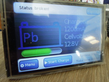
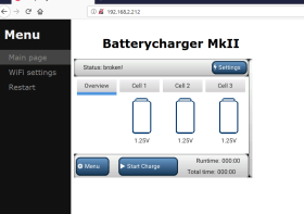
As mentioned we decided to use a raspberry pi TFT with touch for the userinterface. This gives us many new possibilitys to display data and let the user interact with the system. The first thing you see is the main screen, from where you can accessthe main menu. This should be tochfrindly and allow you to change the settings accordingly. At the moment we are using the Littlevgl library in version 5.3 and it seems we need to move now to version 6.0, including cahnges in the API ans some rework in the code. Nevertheless progress is taking place and slowly the parts of the UI become alive. The Wireless part is finished for now and give options we haven't included in the earlier esp32 projects.You can now choose if it is enabled or disabled, also fore it to accesspoint mode with password protection.
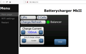
Also some space at the bottom is used to show you the curren state of the wifi network connection. Setting up the charger to wifi shpuld now be an easy job.What also has gotten to life is the chargesettings menu. An even if it looks not that shiny, some nice triks are involved.
The simple scenario using only one cell means just charing with a given a current. Not fancy and nothing special. Things you will expect from a basic charger. If we go a bit further we see we can see some more options.
Balancing is supported and depending on the choosen cell chemistry you also can choose the end of charge voltage. This one is shown for the Lithum based cells. Also the discharge current can be set individually from the charge current.Webinterface, first impressions
Well for the Webinterface we need also to add the ability to have some interaction with the device, meaning a recreation of a bunch of menus, also screenshots with the camera are nice but nit the rea deal. So we added a websocket based remotescreen function to the webinterface. Currently limited to view-only mode, but working.
Besides this little goddie making screenshots possible we will add more and more items to the webinterface in the comming weeks.
DS18B20 a one-wire-way to the temperatures
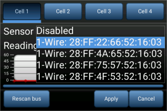
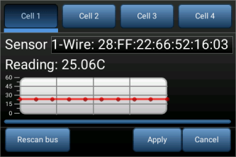
If you charge batteries you will happy to messure the temperature of the charing ones. The prototype currently has one 1-wire-bus you can attach you well priced DS18B20 to. For one cell this will be perfect, also this can be used for the modern batteriepacks to cut off charging the the values are above a certain level. If you have now four cells and four ds18b20 this means a bit of trickery, as you need to map a sensor on the bus to a certain cell to charge. The core logic is implemented and parts of the UI for configuration exist, so you can have four sensors mapped to four cells for messurment.The nice thing about this, we can later reuse the code to build something one of the developer needs for it 19" rack at home. But first a few screenshots form the UI components:
As you can see, we now are able to select a specific 1-Wire sensor to be used with a battery we like to charge. The values will be fetched from the bus using a seperate thread deleivering us every two seconds a new set of values. If you are on an ESP32 and want to read 1-Wire devices, make sure you use a ESP32 optimized lib, else you will get a lot of garbage, as the code for 1-Wire is timing sensetive, and the RTOS ans Flash-Cache is no help to meet this. For now with four sensors the bus is runnign stable and also reporting if one of the sensors is not found any more. Most of the work is currently done unter the hood, so more nice screenshots are a bit difficult. As the temperaturs are now in place the netx one is to the get the balancer voltage and current for the cells.
ESP32 anlog inputs and realtime control ( 6.5.2020 )
The ESP32 is a cheap and powerfull dual core mcu. Looking at the raw numbers ( 240mhz per Core / 4MB Flash and 512kb RAM ) this should be an ideal companion if we want it as core for a battery charger. Other devices have a mcu that is way less powerfull. But there is a catch, specally when doing DC/DC Converter applications like in the battery charger requiered. The ADC is, well, lets be honest, a peace of junk. On paper we have 12Bit Resulution at speeds above 1MSPS, sounds nice, but the results you get are everything but linear. Also the ADC will do some clipping, menaing that we can't messure down to zero volt and also not be able to go upt to 3.3 volt full scale. On the lower side clipping will vvure somwhere arround 0.5 volt and max out somewhere near 2.8 volt. This decreases the range usable to us, to make things even worse the ADC is not working in a linar way. After all you can be happy with many tricks and software correction curves to get in the end near to 8 bit resulution. For many small projects this might be fine, but to decide if we have 4.25 or 4.20 volt in a battery pack, thats someting we won't get from the EPS32. Also running the WiFi will introduce some additional noise to the readings making ugly readings just worst. Last but not least there is one additional catch, that hurts more the audio folks among us, but also has inpact on any other that want to sample data. The analog signals are routed inside the chip throug the IOMUX, so we gain a lot of flexibility, but the price is an analog bandwith of arround 6kHz for signals, as the IOMUX will work as low-pass filter.
This means we will nedd to hook up an external ADC if we want to have usable analog readings and we tested a MAX11614 one, connected via I²C. This gave us usable 12Bit resulution and a decent conversion speed, on paper. In reality we need to deal with some parts of the RTOS runnin gon the two cores limiting the read spead to 200 times a second for four channels with some sideeffects produced by the I²C-Driver used in the ESP32. The next part is the DC/DC Converter, biuld as simple Buck Boost stage controlled by the ESP32. We did some experiments with the statge, and while the Buck part gernerally works, the Boost part was hard to get stable outputting a desired voltage. For the controlloop there are also things like interrupt latency, e.g. you setup a timer to call a function periodically. After the timer fires the interrupt it may takes up to 500 cpu cycles untill you function gets executed. assuming 240Mhz this will lead to 2.1µS delay, a AVR clocked at 16MHz has a simular time to get to an interrupt routine. For controlloops that need fast responses, and a DC/DC Converter is something like this, not ideal. At this point the nasty parts of the ESP32 architecture showed up that heavy, that a change in concept and adjusted it.
Divide and conquer
The charger will be splitted into modular parts. The DC/DC Buck-Boost stage to supply to charge the cells will get its own digital interface, to the ESP32 will just set the desired voltage and current limit. Also this means we will be able to get the output voolateg applied to the cells and the current delivered as digitial values through a defined interface. This information can be slower processed as it would be requiered if we need to take care for the direct control of a DC/DC converter.Also the balancer part is changed. We still need an ADC and a "small" electronic load to be able to discharge cells in a not to long timespan. The electronic load could be opperated by the ESP32, but an MCU with a 12Bit ADC is not much more expensive that an external ADC with the same amount of inputs. This is why we choos the elektronic load and balancer to become its own module for the moment. This means we can test it independently for the ESP32 and the DC/DC stage and may be able to sperate the developement in its onw E-Load project. The same will be true for the DC/DC converter.
PCB prototypes for the ELoad are on its way and we will hopfully be able to provide first images soon.
Discussie (3 opmerking(en))